Tag: Robot

  • inMoov has a Chest

    inMoov has a Chest

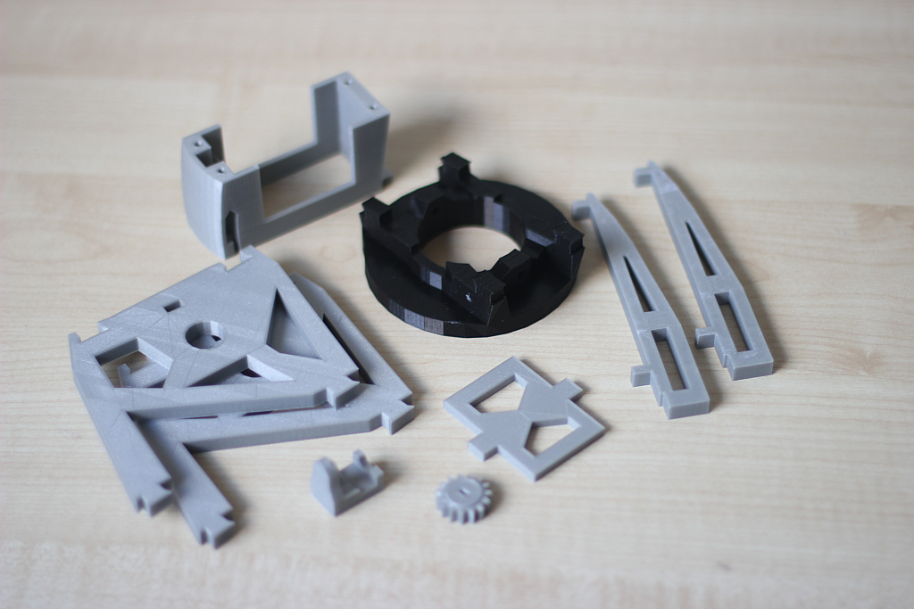
    The world is unfair. My Ultimaker printer had to do more then 70 hours of printing and it took me only 1 hour to put the parts on the inMoov robot. 😉 Below you can see all the parts from the Chest.

    Chestparts

    From left to right and from top to bottom you can see the following parts:

    • ChestTopAttachV1 (right and left part)
    • ChestTopV1 (right and left part)
    • SideRibsCoverV1 (right and left part)
    • ChestRightV1
    • InMrightV1HollowV1 (orange)
    • InMleftV1HollowV1 (orange)
    • ChestLeftV1
    • BottomChestV1(right and left part)
    • MiddleChest+PIRV1
    • UnderKinectV1 (right and left part in black)

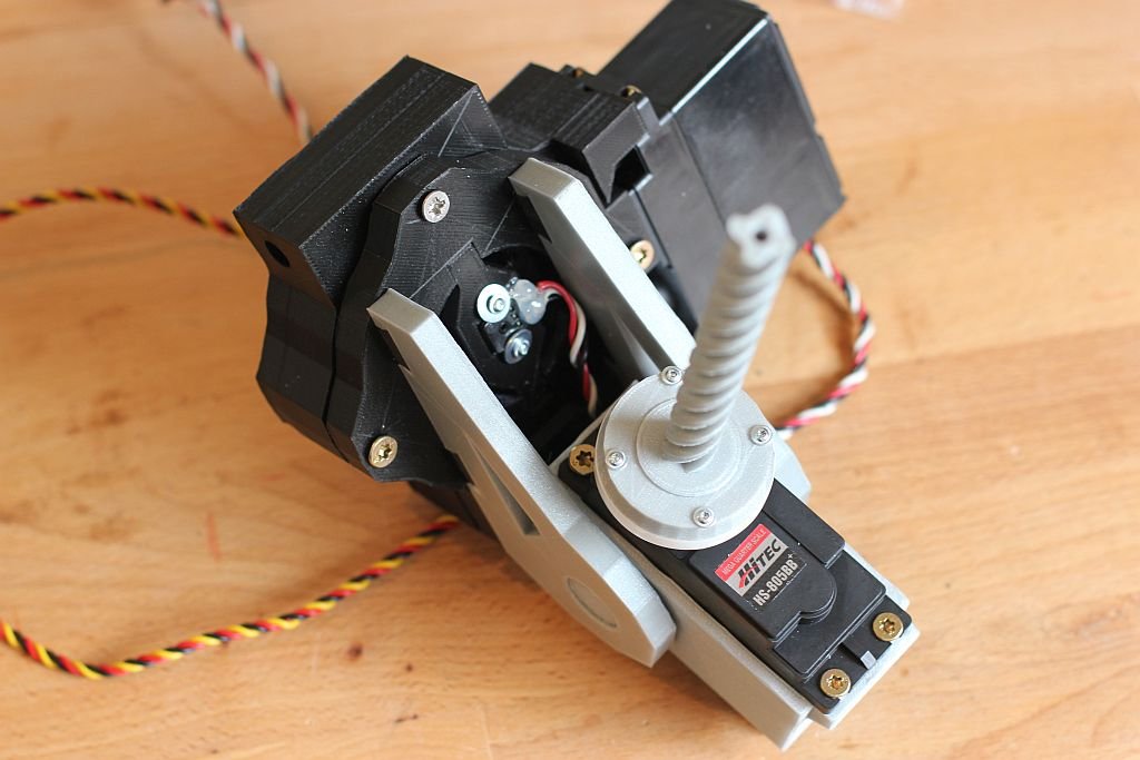
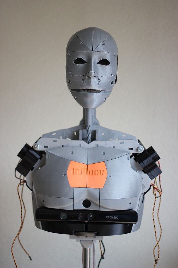
    I am very happy with the results of these prints and they fit really well. The easiest way to mount the chestparts is starting with the ChestRight and ChestLeft together with the InMrightV1Hollow and InMleftHollow. After this you can mount the MiddleChest+PIR and the Kinect. The Kinect is mounted with the UnderKinect parts. I had to push it in with a little bit force to fit it together. I think this was caused by some warping of the prints.

    The inMoov robot gets a PIR sensor to react on people moving by. This is not done yet so you can see a nice hole where the PIR sensor should.

    inMoovChest1 inMoovChest2 inMoovChest3

    Make sure you check the website from Gael Langevin at www.inmoov.fr.

  • Schoulder Inmoov

    Schoulder Inmoov

    The shoulder of the inMoov robot exists of several parts. In this post I describe the build of the parts responsible for the up and down motion of the arm en the back and forward rotation.

    My Ultimaker original with a heated bed prints clean parts most of the time. Only the first layer leaves some burr so I use a file and a knife to remove it.

    The PivWorm part need a lot more work to make it ready to use. First you have to remove the support needed for the worm shape. I used pliers to remove the big parts by breaking it with a little bit of force.

    schoulder1

    After this I needed a knive to remove the supports sticking to the worm part itself. Also the bottom side of the worm needed a file to remove the irregularities.

    schoulder2

    After mounting the PivWorm in it’s casing and adding the PivGear part it did fit as I expected. The strange thing was that the Tooth of the gear where hitting the end of the worm at end closest to the servo. On the InMoov forum this was discussed a few time but it seems not a lot of people experience this problem. I fixed it by using the file again. On the picture below you can see clearly the work I have to make it fit.

    schoulder3

    After this was done it was time to wear it in a little bit. I connected the servo and make it run for 30 minutes and cleaned it afterwards.

    schoulder4

    The gear and worm received a big amount of grease and the housing was closed. The potentiometer was mounted in the square PivPotentio part which is  available on Thingiverse at http://www.thingiverse.com/hairygael/collections/inmoov-parts-and-derivatives. I used a servo motor driver and current meter to see if it worked. At first it did work at it supposed to be and almost break the potentiometer on the right side. The two outside wires on potentiometer should be switched because the angle was measured the wrong way around.

    schoulder5

    A bit of hot glue to secure the wires and prevent the bare wires to touch each other.

    schoulder6

    Next the servo was put in the ServoHolster and the PistionClavi was mounted on the Servo.

    schoulder7

    Then the two parts where connected to each other with the two servoholder parts.

    schoulder8

    On the pictures below you can see the mounted parts on the torso. I also used the square version from potentiometer holder from Thingiverse.

    schoulder9

    schoulder10

    schoulder11

    schoulder9b

    The final result is with the two shoulders attached to the InMoov torso. This is nice progress.

    schoulder12

    Make sure you check the website from Gael Langevin at www.inmoov.fr.

  • InMoov follows own progress

    InMoov follows own progress

    A nice picture of my InMoov robot following it’s own progress.

    immoovfollowsprogress


    Can you guess what part the Ultimaker is making?

    Be sure you check the website from Gael Langevin at www.inmoov.fr.

  • 2 weekend print result

    2 weekend print result

    Because of a holiday  in Turkey I could not print for one week and wasn’t able to share the results with you.

    Printresults

    The picture shows a lot of parts. From left to right and from top to bottom:

    • robpart3V3
    • robpart4V3
    • lowarmsideV1_square
    • rotawrist3V2
    • rotawrist2 (black part)
    • PivPotholderV21b (two black parts)
    • rotawrist1V3
    • cableholderwristV4
    • WristGearsV4 (3 gears)
    • PivPotentioV3 (4 black parts)
    • servo-pulleyX5

    I did redo the lowarmsideV1, PivPotentioV3 and the PivPotholderV21 because I used the original one at frist and used a Dremel to make it fit. The potentiometers fit great is this new design so I made four of them.

    Be sure you check the website from Gael Langevin at www.inmoov.fr.

  • More prints

    More prints

    This weekend my Ultimaker delivered 4 parts. The first part was the LowarmsideV1. I also did this part last weekend, but now I printed it with a square potentiometer mount. The designer of the inMoov, Gael Langevin pointed me to this piece on www.wevolver.com last week. You can find this design on Thingiverse at www.thingiverse.com/hairygael/collections/inmoov-parts-and-derivatives. I like it, because with the left arm I had to modify the hole with my Dremel.

    MorePrints


    In the picture above you can see from left to right and from top to bottom the following pieces.

    • elbowshaftgearV1
    • robpart5V3
    • LowarmsideV1
    • pistonbaseantiV1

    The robpart5V3 is a part for the lower arm and took me over 11 hours to print. I want a nice result so it takes a while. The result is nice. I only removed the print support from the robpart5V3. The parts came out the printer as shown on the picture.

    Be sure you check the website from Gael Langevin at www.inmoov.fr.


  • 4 parts of inMoov robot

    4 parts of inMoov robot

    The Ultimaker Original printed 4 parts from the inMoov Robot this weekend. I wanted to do 2 more parts, but somehow I did not planned it very well. On the picture you can see the 4 print in PLA that came out very nicely.

    • 2 x lowarmsideV1
    • PistonanticlockV1
    • servobaseV1

    inMoov4parts

    Just a few parts to go and the right bicep of the inMoov robot is printed. Make sure that you check out the great website from the designer of this nice robot (www.inmoov.fr).

  • 3 day weekend print

    3 day weekend print

    This weekend it was Easter and in the Nederlands it’s an official national holiday. This means that we have an extra day of free time on Monday. And what can you do when you are at home? Right! Use your printer to make some parts of the inMoov robot. You can see the result of the 3 day weekend on the picture below.

    inMoovLongWeekend

    From left to right and from top to bottom:

    • ServoholderV1
    • RotMitV2
    • 2x reinforcerV1
    • higharmsidev1
    • spacerV1
    • gearHolderV1
    • gearpotentioV1

    These are all part that can be used on both arms. In my case these are all for the right arm. I was happy with the result and I also had time to print a part for a control box of my house. Maybe I write something about it also.

    If you want to make a inMoov robot, please check the designer at www.inmoov.fr


  • Servo hack 2

    Servo hack 2

    I wrote an article (Servo hack) about how to hack a servo for use in the inMoov Robot a while ago. I did a few servo’s back then. Today I did a few more and there where a bit harder to do.

    The motor in the server from the previous batch came loose after a few taps, but with these servos this did not work. The motors where glued to it’s casing.

    To remove the circuit board and the potentiometer I had to desolder the motor from the circuit board. With a small screwdriver under the circuit board and the soldering iron on the leads of the motor I gave it a gentle wiggle a few times from both sides. There are three connections to the motor. The third one is connected to the metal housing of the motor. In the picture below the screwdriver is hidden in my hand.

    IMG_3425

    The motor has big leads and the hole in the circuit board also large so there is also a lot of solder left, after removing the motor. I used solder wick to remove the solder. On the picture below you can see me removing the solder of the third connection.

    IMG_3430

    After cleaning up the circuit board, the rest of the process of the hack is the same as the initial article. It’s time to build it together again after modifying the wiring and the casing . The motor has to be soldered tot the circuit board again. Use enough solder.

    I did three servos and it took me about 1,5 hour.

    IMG_3438

  • inMoov prints

    inMoov prints

    A quick post to show the results of this weekend prints on the Ultimaker. 4 parts of the inMoov shoulder. Please visit www.inmoov.fr for the designer of the inMoov robot.

    IMG_3422

  • inMoov has a head

    Finally I have some progress on my inMoov robot. In my last I described a method to hack servos for the shoulder and the arm, but my inMoov Torso was still headless. The robot has a head now. Yes!!

    IMG_2506

    IMG_0818

    IMG_2505

    IMG_2503

    IMG_2504

    The head of the inMoov robot has a lot of parts. Not only at the outside, but internally there is a mechanism with servos to control the eye and the jaw movement. This needed some tweaks to make it work. First of all I had the wrong servos and these didn’t fit as easy as I expected. The Dremel was needed to make the holes for the servo bigger and another shape. At the end I probably should have designed a new one, but this will do for now

    IMG_2514

    IMG_0819

    Second problem I had, was the mount of the vertical eye movement. The servo arm was too short. I tried everything, but it stayed to short. Finally I designed a new one that was fitted snugly.

    IMG_0820

    As you can see the inner parts aren’t very nice. These actual where the first few parts I printed with my Ultimaker. I used a raft with the print and that isn’t the best method. Now I use a rim to protect the print from warping.

    IMG_2512

    IMG_2500


    At the back of the Neck you see the wires coming out. I used extension wires to make the cable of the servo longer. To guide the wire trough the head I used Tyraps and hot glue. This should protect them from getting stuck between the moving parts.

    IMG_2507

    IMG_0821

    IMG_2511