The inMoov Robot needs a lot of servos. You need multiple servos for the head, shoulders, arms and fingers. The designer Gael Langevin is now developing the hips so we even need more servos (It’s worth it) In most cases we can use standard servos to control various parts of the body. For parts that require a little more torque Geal designed a worm wheel to create more torque. A normal servo can turn for example only 180 degrees and that is sufficient in most cases. The worm wheel has to turn more than the 180 degree a standard servo offers, so we need to modify the servo.
In this example we use a HS805BB+. This is a big and an expensive servo, so be careful and be sure about what you are doing.
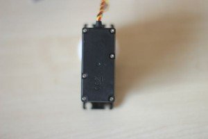
Remove the white disk from the servo spline.
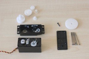
Remove the 6 screws at the bottom of the servo. The bottom plate and the top plate should come off.
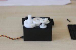
Remove the gears one by one and place them in the right order to put it all together later. As you can see on the picture I put them on the bench the same way as they were on the servo.
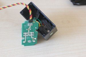
Now its time to remove the motor and electronics from its housing. Hold the servo and gently tap the casing at a small angle on the table at the side where the motor is. After a few gentle taps the motor and the electronics should come loose. If this isn’t working, you can use a screwdriver to push on the axle of the motor at the top side.
Remove the screw on the potentiometer to remove the motor unit.
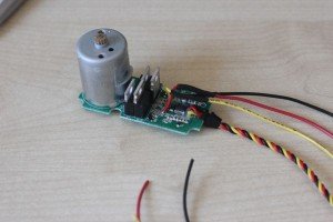
Cut the wires from the servo. Be sure that you keep enough length to solder new wires on to the existing ones. You also can solder new wires on the PCB, but I didn’t do this.
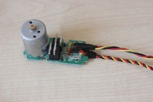
Solder new wires from about 25 cm, at the side of the PCB. In my example I used black instead of the green wire. To protect the wires from touching the metal parts use crimp sockets on each wire.
I also used a crimp socket around these crimp socket to prevent the wires come loose when you pull the wires.
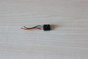
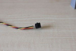
Solder the potentiometer on the new wires. Use the right order to connect them. Sometimes it has to be different than the original connection, because of the different direction from the left and right arm.
Twist the wires from the potentiometer to prevent interference.
After this I tested the servo without the casing. Don’t let anything touch the electronics.
After the electronics the hardware should be changed. On the gear with the outgoing axle is an end tab. I used the Dremel to remove this plastic end tab. You can also use a knife but be careful with that.
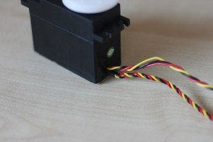
You also need to remove a piece of the casing to run the wires through. In this example I made a hole next to the existing hole. You can also make the existing hole larger to have the wire on top of each other. It depends on you want need.
Put it all together again and test your hack.
Good luck.






I am confused by why the poteniometer needs to be removed from the servo, yet still reconnected? Isn’t the signal controlled by the Arduino? What does the poteniometer due?
Just found your progress log today, thanks for sharing.
Hi John-Paul. The potentiometer is placed on the arm for example to measure the angle of the arm. This is done because of the worm drive. The servo can now rotate several times instead of the 180 degree it used to be. Because of this worm drive the servo can deliver more power, at a cost of speed.