Tag: inMoov

  • More prints

    More prints

    This weekend my Ultimaker delivered 4 parts. The first part was the LowarmsideV1. I also did this part last weekend, but now I printed it with a square potentiometer mount. The designer of the inMoov, Gael Langevin pointed me to this piece on www.wevolver.com last week. You can find this design on Thingiverse at www.thingiverse.com/hairygael/collections/inmoov-parts-and-derivatives. I like it, because with the left arm I had to modify the hole with my Dremel.

    MorePrints


    In the picture above you can see from left to right and from top to bottom the following pieces.

    • elbowshaftgearV1
    • robpart5V3
    • LowarmsideV1
    • pistonbaseantiV1

    The robpart5V3 is a part for the lower arm and took me over 11 hours to print. I want a nice result so it takes a while. The result is nice. I only removed the print support from the robpart5V3. The parts came out the printer as shown on the picture.

    Be sure you check the website from Gael Langevin at www.inmoov.fr.


  • 4 parts of inMoov robot

    4 parts of inMoov robot

    The Ultimaker Original printed 4 parts from the inMoov Robot this weekend. I wanted to do 2 more parts, but somehow I did not planned it very well. On the picture you can see the 4 print in PLA that came out very nicely.

    • 2 x lowarmsideV1
    • PistonanticlockV1
    • servobaseV1

    inMoov4parts

    Just a few parts to go and the right bicep of the inMoov robot is printed. Make sure that you check out the great website from the designer of this nice robot (www.inmoov.fr).

  • 3 day weekend print

    3 day weekend print

    This weekend it was Easter and in the Nederlands it’s an official national holiday. This means that we have an extra day of free time on Monday. And what can you do when you are at home? Right! Use your printer to make some parts of the inMoov robot. You can see the result of the 3 day weekend on the picture below.

    inMoovLongWeekend

    From left to right and from top to bottom:

    • ServoholderV1
    • RotMitV2
    • 2x reinforcerV1
    • higharmsidev1
    • spacerV1
    • gearHolderV1
    • gearpotentioV1

    These are all part that can be used on both arms. In my case these are all for the right arm. I was happy with the result and I also had time to print a part for a control box of my house. Maybe I write something about it also.

    If you want to make a inMoov robot, please check the designer at www.inmoov.fr


  • Servo hack 2

    Servo hack 2

    I wrote an article (Servo hack) about how to hack a servo for use in the inMoov Robot a while ago. I did a few servo’s back then. Today I did a few more and there where a bit harder to do.

    The motor in the server from the previous batch came loose after a few taps, but with these servos this did not work. The motors where glued to it’s casing.

    To remove the circuit board and the potentiometer I had to desolder the motor from the circuit board. With a small screwdriver under the circuit board and the soldering iron on the leads of the motor I gave it a gentle wiggle a few times from both sides. There are three connections to the motor. The third one is connected to the metal housing of the motor. In the picture below the screwdriver is hidden in my hand.

    IMG_3425

    The motor has big leads and the hole in the circuit board also large so there is also a lot of solder left, after removing the motor. I used solder wick to remove the solder. On the picture below you can see me removing the solder of the third connection.

    IMG_3430

    After cleaning up the circuit board, the rest of the process of the hack is the same as the initial article. It’s time to build it together again after modifying the wiring and the casing . The motor has to be soldered tot the circuit board again. Use enough solder.

    I did three servos and it took me about 1,5 hour.

    IMG_3438

  • inMoov prints

    inMoov prints

    A quick post to show the results of this weekend prints on the Ultimaker. 4 parts of the inMoov shoulder. Please visit www.inmoov.fr for the designer of the inMoov robot.

    IMG_3422

  • inMoov has a head

    Finally I have some progress on my inMoov robot. In my last I described a method to hack servos for the shoulder and the arm, but my inMoov Torso was still headless. The robot has a head now. Yes!!

    IMG_2506

    IMG_0818

    IMG_2505

    IMG_2503

    IMG_2504

    The head of the inMoov robot has a lot of parts. Not only at the outside, but internally there is a mechanism with servos to control the eye and the jaw movement. This needed some tweaks to make it work. First of all I had the wrong servos and these didn’t fit as easy as I expected. The Dremel was needed to make the holes for the servo bigger and another shape. At the end I probably should have designed a new one, but this will do for now

    IMG_2514

    IMG_0819

    Second problem I had, was the mount of the vertical eye movement. The servo arm was too short. I tried everything, but it stayed to short. Finally I designed a new one that was fitted snugly.

    IMG_0820

    As you can see the inner parts aren’t very nice. These actual where the first few parts I printed with my Ultimaker. I used a raft with the print and that isn’t the best method. Now I use a rim to protect the print from warping.

    IMG_2512

    IMG_2500


    At the back of the Neck you see the wires coming out. I used extension wires to make the cable of the servo longer. To guide the wire trough the head I used Tyraps and hot glue. This should protect them from getting stuck between the moving parts.

    IMG_2507

    IMG_0821

    IMG_2511

  • Servo Hack

    The inMoov Robot needs a lot of servos. You need multiple servos for the head, shoulders, arms and fingers. The designer Gael Langevin is now developing the hips so we even need more servos (It’s worth it) In most cases we can use standard servos to control various parts of the body. For parts that require a little more torque Geal designed a worm wheel to create more torque. A normal servo can turn for example only 180 degrees and that is sufficient in most cases. The worm wheel has to turn more than the 180 degree a standard servo offers, so we need to modify the servo.

    In this example we use a HS805BB+. This is a big and an expensive servo, so be careful and be sure about what you are doing.

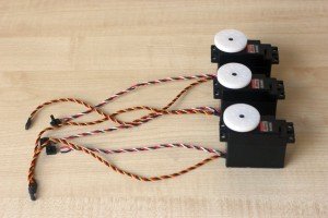
    Remove the white disk from the servo spline.

    servohack1

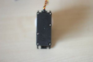
    Remove the 6 screws at the bottom of the servo. The bottom plate and the top plate should come off.

    Servohack2

    Servohack3


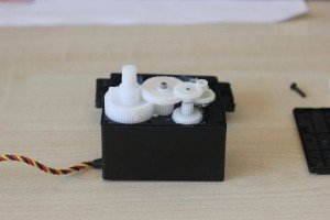
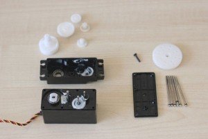
    Remove the gears one by one and place them in the right order to put it all together later. As you can see on the picture I put them on the bench the same way as they were on the servo.

    servohack4

    servohack5

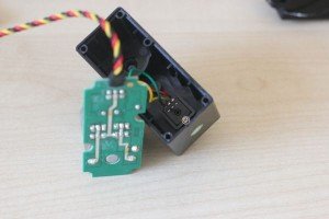
    Now its time to remove the motor and electronics from its housing. Hold the servo and gently tap the casing at a small angle on the table at the side where the motor is. After a few gentle taps the motor and the electronics should come loose. If this isn’t working, you can use a screwdriver to push on the axle of the motor at the top side.

    Remove the screw on the potentiometer to remove the motor unit.

    servohack6

    Cut the wires from the servo. Be sure that you keep enough length to solder new wires on to the existing ones. You also can solder new wires on the PCB, but I didn’t do this.

    Servohack7

    servohack8

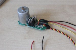
    Solder new wires from about 25 cm, at the side of the PCB. In my example I used black instead of the green wire. To protect the wires from touching the metal parts use crimp sockets on each wire.

    I also used a crimp socket around these crimp socket to prevent the wires come loose when you pull the wires.

    servohack9

    servohack10

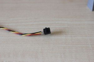
    Solder the potentiometer on the new wires. Use the right order to connect them. Sometimes it has to be different than the original connection, because of the different direction from the left and right arm.

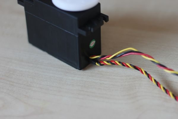
    Twist the wires from the potentiometer to prevent interference.

    servohack11

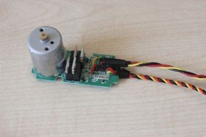
    After this I tested the servo without the casing. Don’t let anything touch the electronics.

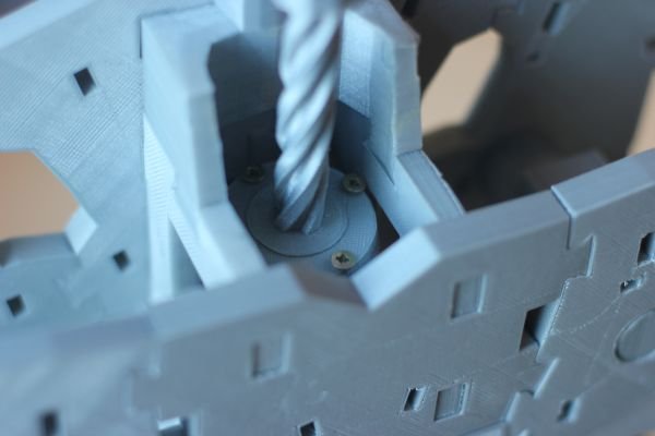
    After the electronics the hardware should be changed. On the gear with the outgoing axle is an end tab. I used the Dremel to remove this plastic end tab. You can also use a knife but be careful with that.

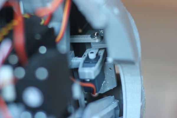
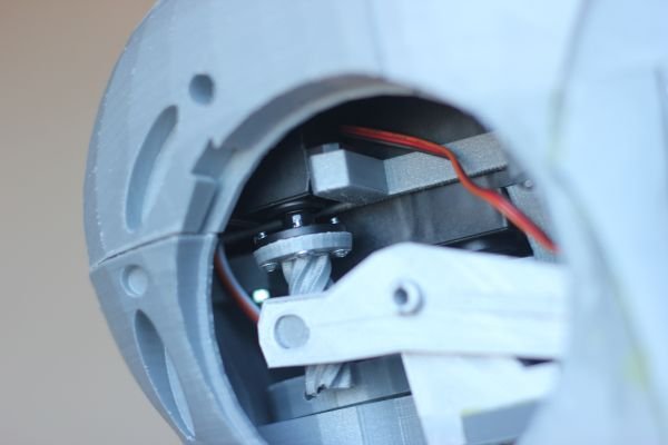
    You also need to remove a piece of the casing to run the wires through. In this example I made a hole next to the existing hole. You can also make the existing hole larger to have the wire on top of each other. It depends on you want need.

    servohack12

    servohack13

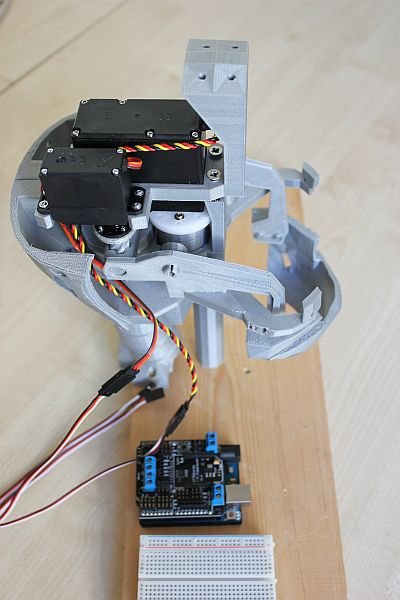
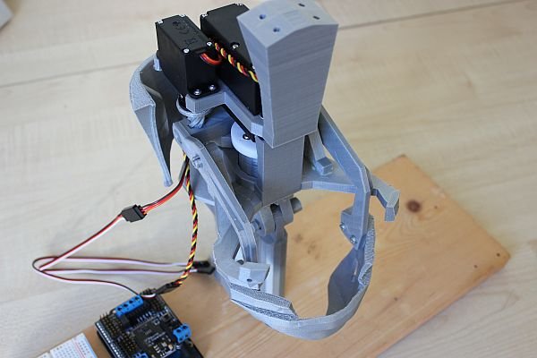
    Put it all together again and test your hack.

    servohack14

    Good luck.

  • inMoov torso on a stick

    All the parts of the InMoov torso are ready and I have put it together.
    Yes!!!! The torso is the main body part of the InMoov because the head and the arms are attached to it.

    mount1

    To make the torso stand up I used the two part stand holder from http://www.thingiverse.com/thing:44452. I want to mount the Kinect and this part make this possible and is robust enough. Those two parts are glued together. The metal pipe is 22 mm and is 1 meter long.

    The hole in stand holder part is slightly smaller so I used a 22 mm drill to make it bigger.

    mount2

    At the bottom I used two pieces of wood I had lying around and used some screws and glue to mount it together.

    mount3

    This construction will not be stable enough when moving the arms. For now it’s enough because a lot of printing is required to finish the arms.

    While printing the arms I can complete the head and mount the Kinect. Some extra pictures of the torso.

    mount4

    mount5

    Make sure you take a look at the website from InMoov at www.inmoov.fr

  • Progress inMoov torso

    Slowly but surely the InMoov torso is taking shape. There are a lot of parts to print. I damaged my Ultimaker printer by pulling to hard at the filament. I had to wait for spare parts, but I am printing again. In the pictures you can see the torso with only three parts missing at the back side.

    I will be happy if this is done, so I can mount the torso on a stick and the head on top of it. The part fit together very well without a lot of modifying afterwards. Please take a look at the original designer of the inMoov robot. www.inmoov.fr

    torso1

    torso2

    torso3

    torso4

  • Servo’s in inMoov head

    To complete my inMoov head I had to do two things. Mounting the jaw with its servo and the eye mechanism. The jaw part is done now and it is working fine.

    The servo has to turn just a little bit to open and close the jaw completely. It’s quite smooth. I have used a cheap Modelcraft
    RS2 servo. I am not sure how long this will work, but it good for now. The servo is mounted with four 2,5mmx8mm TORX self tapping screws with a small ring at the head. There are just bigger than the mounting holes of the servo. I don’t like it but it will hold.

    IMG_0339

    IMG_0336


    On the picture you can also see the bigger servo for turning the head from left to right. It’s a HS805BB Mega Quarter Scale servo from Hitec. One side is mounted with M3 bolts and nuts. On the opposite side I used phillip head screws I had lying around because your can’t use bolts in those holes.

    IMG_0337

    Gael Langevin is the designer of this robot. Be sure to visit his website
    at http://www.inmoov.fr/