The shoulder of the inMoov robot exists of several parts. In this post I describe the build of the parts responsible for the up and down motion of the arm en the back and forward rotation.
My Ultimaker original with a heated bed prints clean parts most of the time. Only the first layer leaves some burr so I use a file and a knife to remove it.
The PivWorm part need a lot more work to make it ready to use. First you have to remove the support needed for the worm shape. I used pliers to remove the big parts by breaking it with a little bit of force.

After this I needed a knive to remove the supports sticking to the worm part itself. Also the bottom side of the worm needed a file to remove the irregularities.

After mounting the PivWorm in it’s casing and adding the PivGear part it did fit as I expected. The strange thing was that the Tooth of the gear where hitting the end of the worm at end closest to the servo. On the InMoov forum this was discussed a few time but it seems not a lot of people experience this problem. I fixed it by using the file again. On the picture below you can see clearly the work I have to make it fit.

After this was done it was time to wear it in a little bit. I connected the servo and make it run for 30 minutes and cleaned it afterwards.

The gear and worm received a big amount of grease and the housing was closed. The potentiometer was mounted in the square PivPotentio part which is available on Thingiverse at http://www.thingiverse.com/hairygael/collections/inmoov-parts-and-derivatives. I used a servo motor driver and current meter to see if it worked. At first it did work at it supposed to be and almost break the potentiometer on the right side. The two outside wires on potentiometer should be switched because the angle was measured the wrong way around.

A bit of hot glue to secure the wires and prevent the bare wires to touch each other.

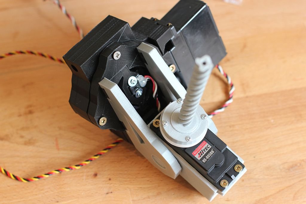
Next the servo was put in the ServoHolster and the PistionClavi was mounted on the Servo.

Then the two parts where connected to each other with the two servoholder parts.
On the pictures below you can see the mounted parts on the torso. I also used the square version from potentiometer holder from Thingiverse.


The final result is with the two shoulders attached to the InMoov torso. This is nice progress.

Make sure you check the website from Gael Langevin at www.inmoov.fr.

