The bicep from the inmoov is not a complex part and are the same for both left and right arm. The covers are sometimes a struggle to mount because in my case the print is a bit taller then it should be.
My Servo (Hitec HS-805BB+) has a square potentiometer so this doesn’t fit in the orginal LowArmSideV1 version from Gaël . I found a LowArmSideV1 with a square hole on Thingiverse by alansrobotlab (https://www.thingiverse.com/thing:533469). This part receives the square potentiometer snugly.
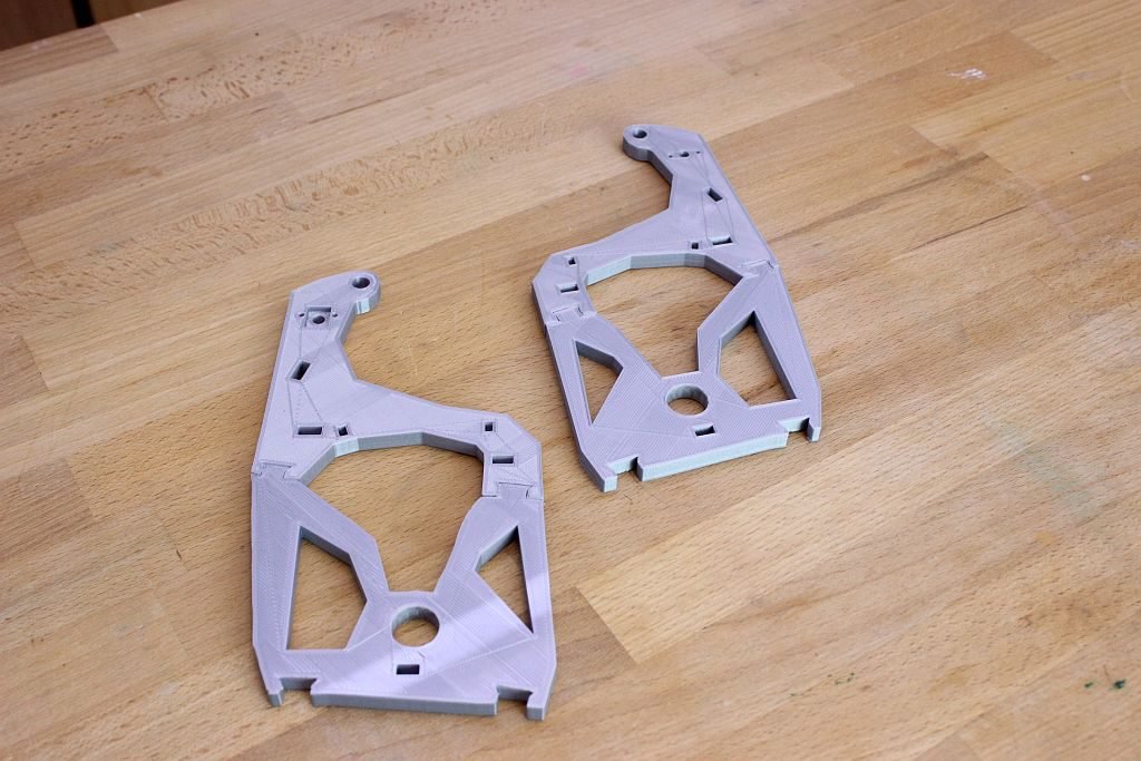
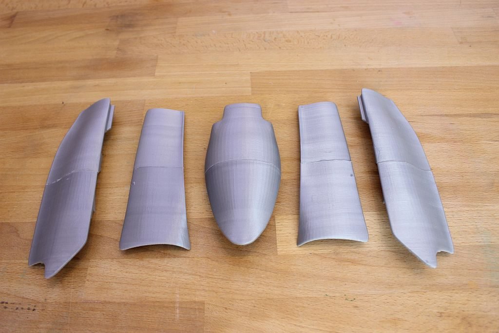
Let’s start. I started with gluing the HighArmSide and the LowArmSide parts together twice. Only a few adjustments where needed with sanding paper and a file.
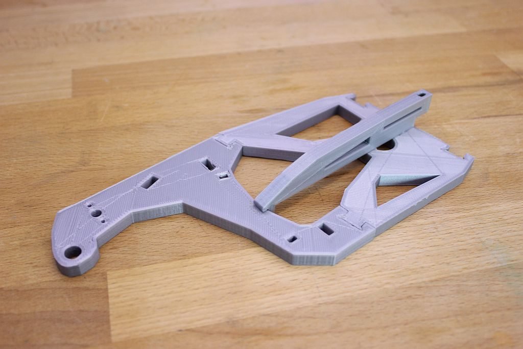
After this the Reinforcer was added to both sides. I used glue to make a strong connection between the parts.
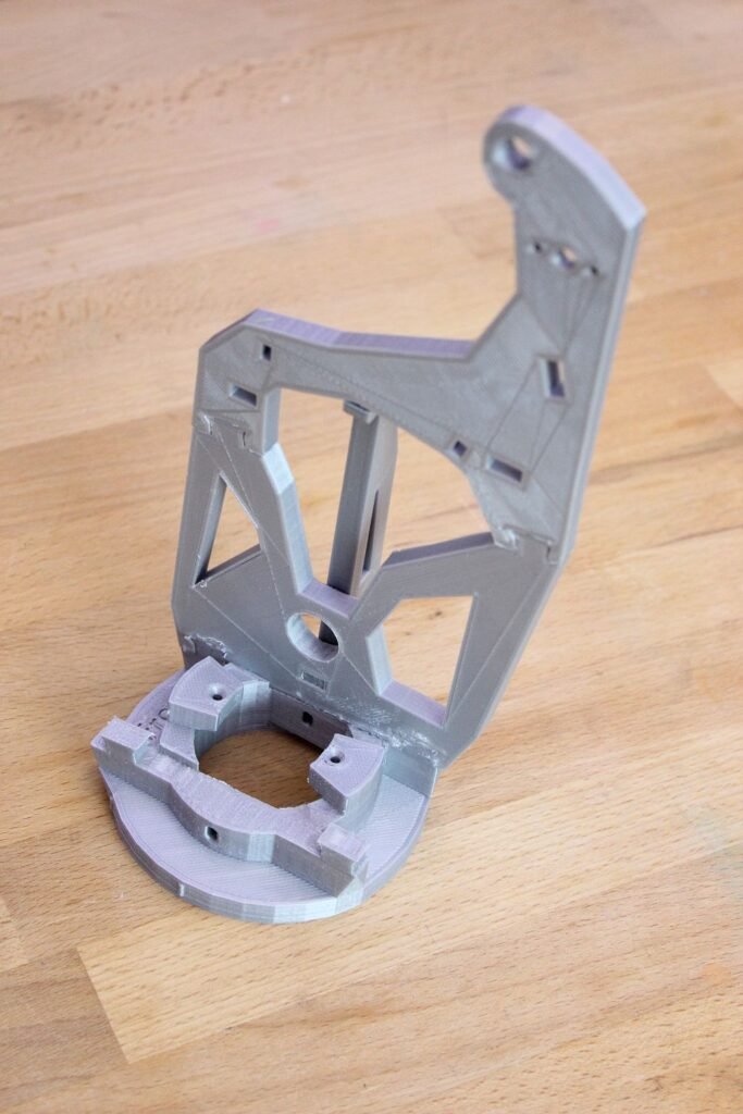
Then I glued one of the sides to the RotMid. I didn’t glue the other side, because I want to be able to remove one side, if something is wrong.
The gears from Pistonanticlock and the Pistonbaseanti prints had some rough edges. I sanded these parts a little bit and then I rotated the piston over and over again in the Piston base. I went back and forth with the sandpaper and after a while it rotated nicely. The Pistonbaseanti needed some adjustments on the axle on the sides. In my case the axle was not completely round, but more like an oval shape. I used a file and sandpaper to make it as round as possible. I also made the holes from the arm sides a little bit bigger.
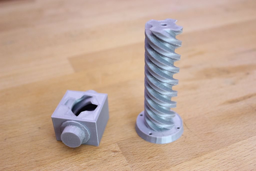
The Pistonbaseanti fits together with the Spacer between the two sides.

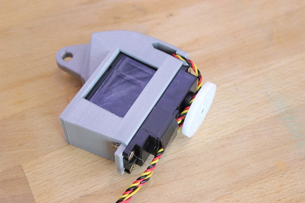
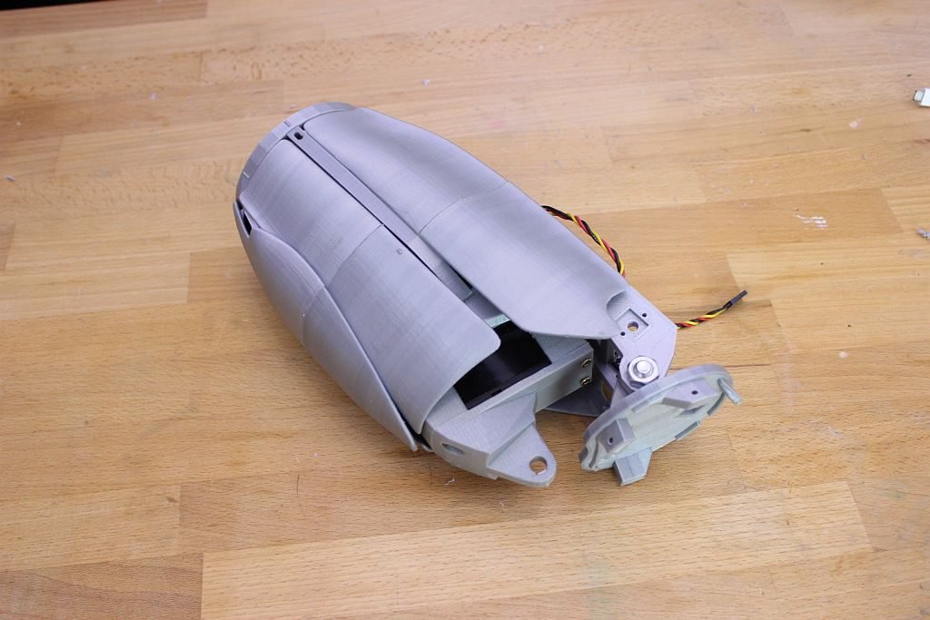
The Servobase and the Servoholder are mounted together with screws so you can replace the servo if it breaks down. I used screws with a diameter of 3,5 mm and a length of 16 mm. The wires from the modified servo need to go through the holes on the side of the Servoholder. The potentiometer is to large and has to be detached from the servo. The wires have to be guided through the channel on the side, so the wires don’t get squashed by other parts of the bicep. I used thicker wire then intended, so I had to make the channel for the wire a bit bigger. A drop of hot glue keeps them in place. To guide the wires over the servo I used black tape.
To mount the Pistonanticlock on the servo I made the four holes bigger with a 3 mm drill. Then I used a screw with a diameter of 3 mm and a length of 16mm. My screws where to long so I had to file them to the right length.

Then I fitted the Pistonanticlock and the Pistonbaseanti together by turning the servo manually.

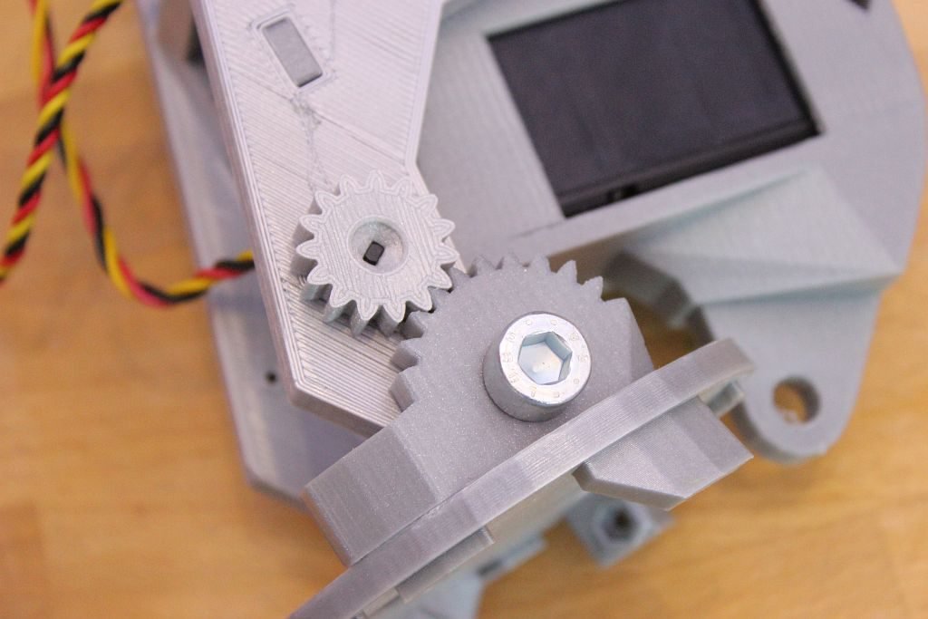
The Elbowshaftgear and the Robcap are glued together and then mounted on the bicep with a 8mm bolt.
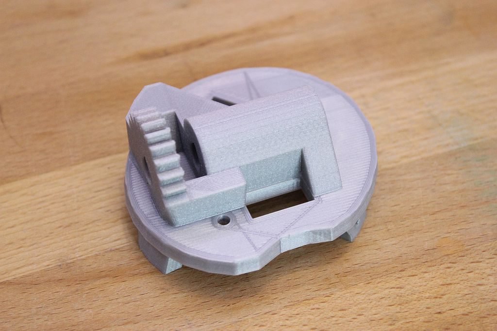
My potentiometer fits nicely in the square hole. It doesn’t need any screws now, but maybe I will add them later. On the potentiometer the Gearpotentio is mounted. The Gearholder then is slided over the gear to prevent is from sliding off.


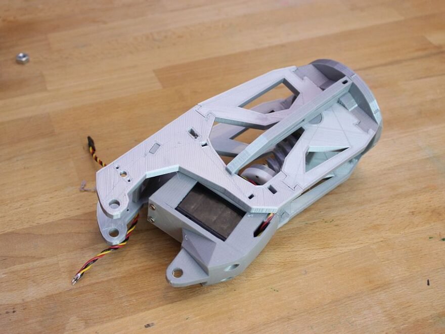
The last step in this assembly is to glue all covers together and mount them on the bicep. It’s looks a lot cooler with the covers on. I needed to file some parts because it didn’t fit.

In the next episode I am going to build the lower arm and will connect the arm to the shoulders part of the inMoov. If you have questions or comments, please let me know. inMoov is designed by Gaël Langevin so make sure you visit is website at https://inmoov.fr
Comments
2 responses to “inMoov Robot Bicep”
This is a really nice assembly tutorial, with some great photos, thanks for sharing. The LowArmSide has since been updated on the inmoov.fr website to accept the square potentiometer, but the part you suggested also works great.
I don’t believe you mentioned what model of servo you used. Like you, I did not insulate the wires where I soldered them onto the potentiometer. This caused a problem later because they shorted out on mine.
The main part missing from your article is how to modify the servo. This is not a trivial step and probably requires an article of it’s own.
Hello Stephen, Thank you for you reply. You are right about the uninsulated servo wires, but I didn’t have problems so far. I mention the servo type at the beginning of the article. On the following pages Servo Hack and Servo Hack 2, I explain how to modify the servo. I also took a look at your website http://inmoov.civrays.com and your inMoov robot is getting along nice.