Tag: Project

  • 4 parts of inMoov robot

    4 parts of inMoov robot

    The Ultimaker Original printed 4 parts from the inMoov Robot this weekend. I wanted to do 2 more parts, but somehow I did not planned it very well. On the picture you can see the 4 print in PLA that came out very nicely.

    • 2 x lowarmsideV1
    • PistonanticlockV1
    • servobaseV1

    inMoov4parts

    Just a few parts to go and the right bicep of the inMoov robot is printed. Make sure that you check out the great website from the designer of this nice robot (www.inmoov.fr).

  • 3 day weekend print

    3 day weekend print

    This weekend it was Easter and in the Nederlands it’s an official national holiday. This means that we have an extra day of free time on Monday. And what can you do when you are at home? Right! Use your printer to make some parts of the inMoov robot. You can see the result of the 3 day weekend on the picture below.

    inMoovLongWeekend

    From left to right and from top to bottom:

    • ServoholderV1
    • RotMitV2
    • 2x reinforcerV1
    • higharmsidev1
    • spacerV1
    • gearHolderV1
    • gearpotentioV1

    These are all part that can be used on both arms. In my case these are all for the right arm. I was happy with the result and I also had time to print a part for a control box of my house. Maybe I write something about it also.

    If you want to make a inMoov robot, please check the designer at www.inmoov.fr


  • Servo hack 2

    Servo hack 2

    I wrote an article (Servo hack) about how to hack a servo for use in the inMoov Robot a while ago. I did a few servo’s back then. Today I did a few more and there where a bit harder to do.

    The motor in the server from the previous batch came loose after a few taps, but with these servos this did not work. The motors where glued to it’s casing.

    To remove the circuit board and the potentiometer I had to desolder the motor from the circuit board. With a small screwdriver under the circuit board and the soldering iron on the leads of the motor I gave it a gentle wiggle a few times from both sides. There are three connections to the motor. The third one is connected to the metal housing of the motor. In the picture below the screwdriver is hidden in my hand.

    IMG_3425

    The motor has big leads and the hole in the circuit board also large so there is also a lot of solder left, after removing the motor. I used solder wick to remove the solder. On the picture below you can see me removing the solder of the third connection.

    IMG_3430

    After cleaning up the circuit board, the rest of the process of the hack is the same as the initial article. It’s time to build it together again after modifying the wiring and the casing . The motor has to be soldered tot the circuit board again. Use enough solder.

    I did three servos and it took me about 1,5 hour.

    IMG_3438

  • inMoov prints

    inMoov prints

    A quick post to show the results of this weekend prints on the Ultimaker. 4 parts of the inMoov shoulder. Please visit www.inmoov.fr for the designer of the inMoov robot.

    IMG_3422

  • The HC-SR04 project

    Yes. Another project is published today. This project is all about the HCSR04 ultrasonic ranging module. This not to expensive sensor is great for robot projects. In this project I explain how to use it with an Arduino.

    You can find the project at https://swanrobotics.com/HCSR04_Project .

  • GP2D12 Project added

    On the last day of the year I managed to add a new project after a long time. This little project is all
    about the GP2D12 sensor. With this sensor you can measure the distance to an object in front of your
    robot. You can find the project https://swanrobotics.com/projects/gp2d12_project/

  • Update on the Wireless Arduino Project

    I got a remark from Johan because he found out that you have to disconnect the APC220 before uploading the sketch. I have added it to project page.  https://swanrobotics.com/Wireless_Arduino

  • New project with Arduino

    Today I published a small project to measure voltage with an Arduino. This has great use for checking the battery of your mobile robot.
    See https://swanrobotics.com/projects/voltagedivider/ for the article.

  • Microbug

    The holiday last week gave me the opportunity to shop in a little electronics, RC and other things store. I bought a microbug kit (MK127) from Velleman for almost 12 Euro. After doing complex robot things it was time to do a simple project and make my kids enthusiastic about robotics.

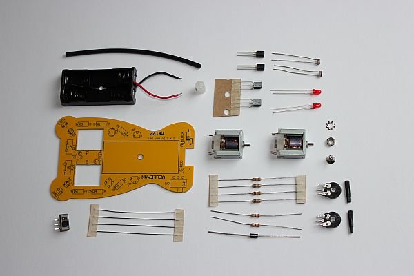
    The electronics basically exists of two separate circuits each driving a motor to make sure the microbug is moving towards the light. The kit contains everything you need make this microbug work except for the batteries. You need a soldering iron, a screwdriver and a file.

    MicrobugParts

    I didn’t like the instruction because it’s a little bit messy, but everything is on there. Just place the components on it from small to big and use the soldering iron. The tricky thing is mounting the motors.

    MicrobugFront

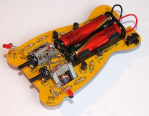
    They need to be roughened after which you can fix them with solder. Make sure you mount them with the right side up, because I didn’t. The polarity of the motors was switched and the microbug was moving away from the light. Also funny ofcourse, but this was not the expected result. When the motors are fixed it’s not easy to remove them again.

    MicrobugBack

    I didn’t rotate them and used gray wire to make the right connections. Those gray wires just look there tiny brain.

    If you have a little experience in soldering you should be able to make it work under one hour. After that you can let the kids in with their flashlight. Of course after you tested it yourselves.

  • Published Article on Fritzing.org

    The Arduino wireless APC220 project is now published on http://Fritzing.org to share it to a broader public. See http://fritzing.org/projects/wireless-arduino-with-apc220.