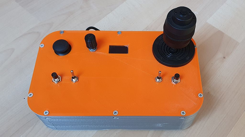
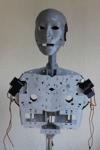
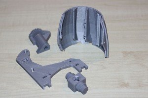
To control a robot, I wanted to see if ESP-NOW, a communication method developed explicitly for the ESP family, would work. This project aims to determine whether ESP-NOW provides a reliable connection over a reasonable distance and whether ESP-NOW can send sufficient data back and forth.
ESP-NOW makes it possible to set up different types of communication:
- One-way communication
- One master and multiple slaves
- One slave and multiple masters
- Two-way communication
- Multiple-way communication (a network of ESP boards)
In my example, I use the two-way communication protocol to build a remote control that can operate a robot. The robot must also send data back. If you want to read more about the possibilities and background of ESP-NOW, check out this excellent source of information:
https://randomnerdtutorials.com/esp-now-esp32-arduino-ide/
Setup
My first test setup consists of the following components:
Board 1
- Joystick (Sends signal)
- Prints the distance from the distance sensor via Serial
Board 2
- Servo (Uses X position from the joystick)
- HC-SR04 distance sensor mounted on the servo
- Prints the distance from the distance sensor via Serial
The joystick on the master board controls the servo on the slave board. The distance sensor rotates along with the servo, and the measured distance is sent back to the master board. The setup is simple, and it gives a first impression of the speed and reliability of the ESP-NOW connection.
BOM (Bill of Materials)
In this project, I used:
- DOIT ESP32 DEVKIT V1
- ESP32S 38P/V4/Goouuu Expansion board
- ESP32/V4/Goouuu Terminal Adapter Expansion board
- Dual-axis XY Joystick Module
- Tower Pro Micro Servo SG90
- HC-SR04 Distance sensor
- Level Converter board
- Jumpwires
- 3D printed parts (Optional)
Of course, you can use different components if you want — no problem at all.
Preparation
To use ESP-NOW, you need to know the MAC addresses of the ESP boards. It is essential to send data to the correct board. You can find this easily by uploading the following code and reading the MAC address via the Serial Monitor in the Arduino IDE:
#include "WiFi.h"

void setup(){
  Serial.begin(115200);
  WiFi.mode(WIFI_MODE_STA);
  Serial.println(WiFi.macAddress());
}

void loop(){
}
Once uploaded, open the Serial Monitor and press the reset button on the DOIT board, and the MAC address will appear.
Build
Once we know the MAC addresses, we can start building the setup. I’m using parts from Evenblox to keep everything neatly together and make it easier to transport. You can find these parts and more information on https://www.evenblox.com. Also, check out this great 3D model for mounting your sensor: HCSR04 mount for SG90 servo by rjlew – Thingiverse
Below you’ll find the schematic of board one (Master) and a photo of the breadboard setup:

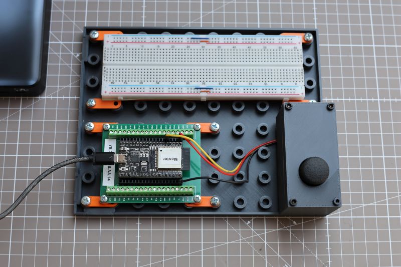
Next is the schematic of board 2 (Slave) and a photo of its setup:

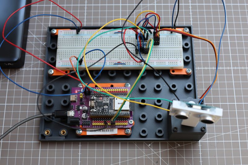
I’m using the HC-SR04 sensor to measure distance. I’ve written an article about this before — check it out here: HC-SR04 Project – SwanRobotics.
The servo and the HC-SR04 both run on 5V. The ESP32 operates at 3.3V, so a level converter is needed. There are HC-SR04 versions that support both 3.3V and 5V, but the one used in this project does not. For more information about level converters, check out Level Converter – SwanRobotics.
Alternatively, you could use the HC-SR04P sensor, which supports both 3.3V and 5V directly.
Code
The code is available on GitHub. Remote_control_test_ESP-NOW
You’ll need to update the MAC addresses in the code to make it work for your setup. The code handles several tasks:
The remote sends a heartbeat every 200 ms. A heartbeat is essential when the system controls an actual robot. The robot checks for incoming data. If no data comes in, the servo returns to its middle position.
The joystick value is sent to the robot, which reads it and converts it to a servo position.
The sensor measures the distance and sends it back to the remote.
The data from both ESP boards can be monitored via the Serial Monitor in the Arduino IDE, making it easy to test the connection in different locations.
Once the code is uploaded, it should be possible to view the correct data.
What’s Next
This setup works well, and the ESP boards pass data smoothly. I want to test how far the boards can communicate in different environments (home, street, forest), so I’ll add a display to the remote control to show the connection status. That way, I can see when the signal is lost. The joystick is sensitive near the center position, so I plan to smooth that out in software.
