Now we are going to put the back covers in place. This is a fairly easy build. Just print all parts and clean them up. It’s important to put all the mounts in place first. The panels should be glued together on the robot itself because to prevent to much stress on the parts.
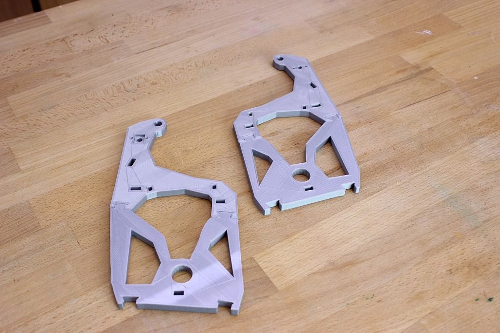
On the following picture, the parts are layed out as they should be mounted.
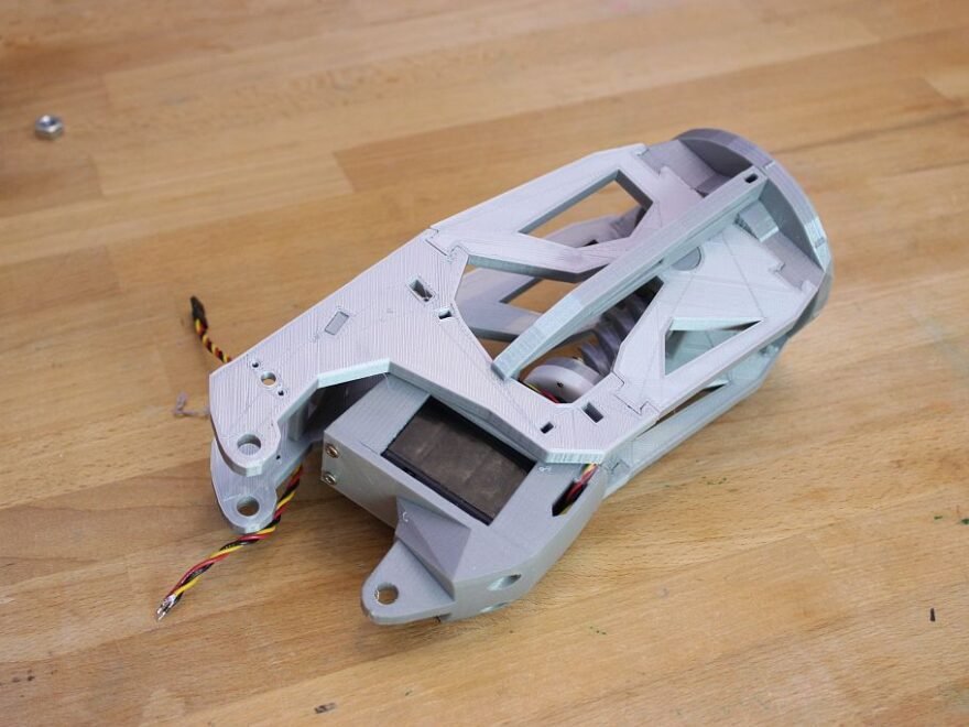
The top part of the back covers should look like this. I used super glue to glue the PLA parts together. Those cheap clamps are usefull to keep everything aligned.
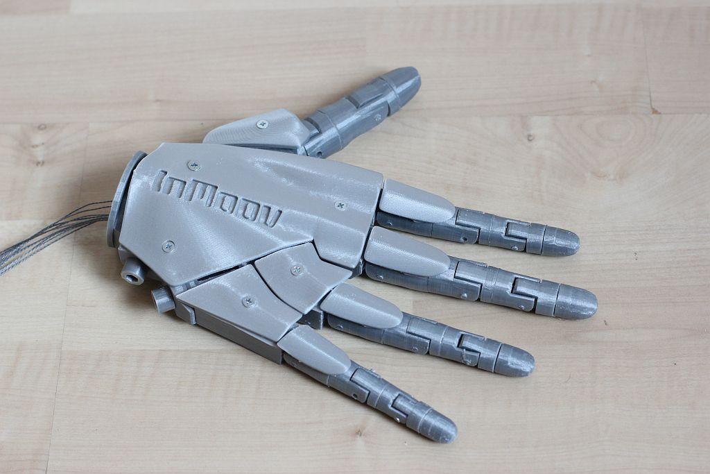
At the end you should see something like this.
If you have questions or comments, please let me know. inMoov is designed by Gaël Langevin so make sure you visit is website at https://inmoov.fr.
Finally I
made some progress on inMoov robot in a long time. The left arm is completely
done already, but the right side still needs the lower arm and the right hand.
In this article we going to look at the right hand.
I made a
video with every step of the build in detail, so you can follow along. inMoov
is designed by Gaël Langevin so make sure you visit is website at https://inmoov.fr.
I always
print the parts with a brim so it needs a lot of cleanup, but it makes sure the
parts are nice and straight. This is important if you need to glue parts
together. After cleaning up it’s a good thing to lay all the part on the table
to see if everything is there.
I found it a little bit confusing how the fingers should be glued together, but it’s fairly simple If you know where to look at.
The lower
part of the finger has a marking in the shape of a rectangle when the parts are
glued together. The top cap should be glued together with the part with two
small holes on the top for the wires. I use hot glue for this part so I can
remove the cap if I have to replace the wires someday. For the other parts I
used Super Glue. The middle parts of the finger have a shape on the face where
the two parts come together.
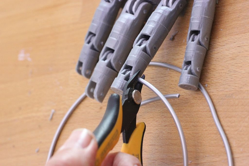
For the
rotating part I used a piece of filament and cut it with a small wire cutter to
make a straight cut.
.
The other
parts are not too complicated to fit together, with help of the picture below.
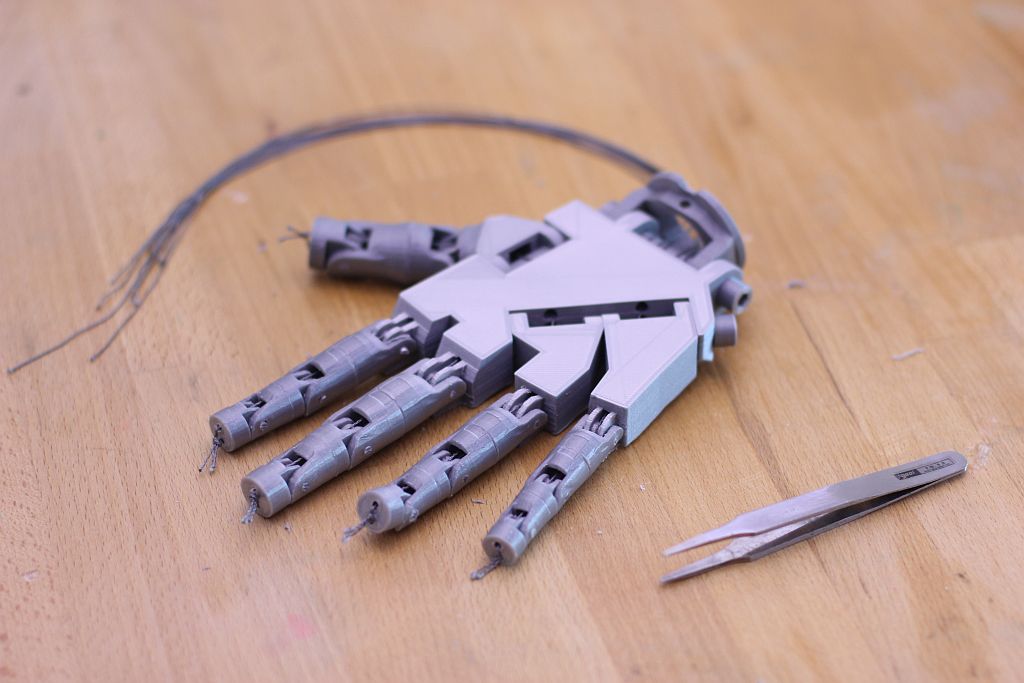
You need
a tweezer to put the wires through the fingers and the hand. It’s not easy but
with some patients it’s not impossible.
At last I
mounted the top of the hand with some 3 mm screws. The 4 parts on the fingers
are glued on the fingers. I made the mistake once to glue them on the hand and
that looks strange when the hand is in closed position.
If you
have questions or comments, please let me know. inMoov is designed by Gaël
Langevin so make sure you visit is website at https://inmoov.fr
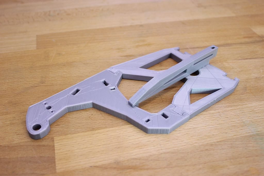
The bicep
from the inmoov is not a complex part and are the same for both left and right
arm. The covers are sometimes a struggle to mount because in my case the print
is a bit taller then it should be.
My Servo (Hitec HS-805BB+) has a square potentiometer so this doesn’t fit in the orginal LowArmSideV1 version from Gaël . I found a LowArmSideV1 with a square hole on Thingiverse by alansrobotlab (https://www.thingiverse.com/thing:533469). This part receives the square potentiometer snugly.
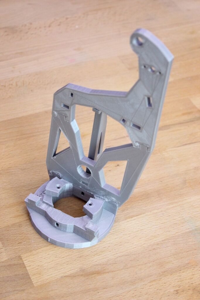
Let’s
start. I started with gluing the HighArmSide and the LowArmSide parts together
twice. Only a few adjustments where needed with sanding paper and a file.
After
this the Reinforcer was added to both sides. I used glue to make a strong
connection between the parts.
Then I
glued one of the sides to the RotMid. I didn’t glue the other side, because I
want to be able to remove one side, if something is wrong.
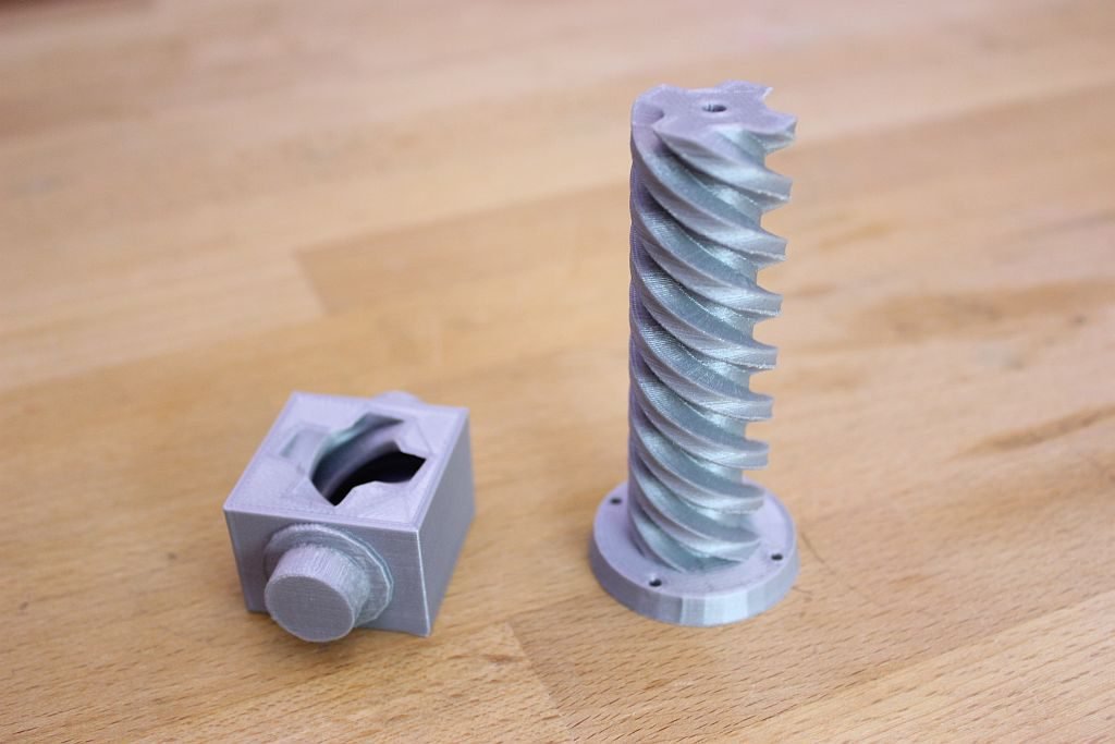
The gears from Pistonanticlock and the Pistonbaseanti prints had some rough edges. I sanded these parts a little bit and then I rotated the piston over and over again in the Piston base. I went back and forth with the sandpaper and after a while it rotated nicely. The Pistonbaseanti needed some adjustments on the axle on the sides. In my case the axle was not completely round, but more like an oval shape. I used a file and sandpaper to make it as round as possible. I also made the holes from the arm sides a little bit bigger.
The Pistonbaseanti
fits together with the Spacer between the two sides.
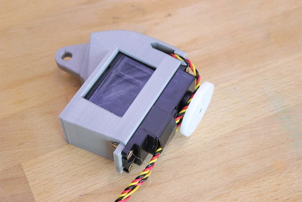
The Servobase and the Servoholder are mounted together with screws so you can replace the servo if it breaks down. I used screws with a diameter of 3,5 mm and a length of 16 mm. The wires from the modified servo need to go through the holes on the side of the Servoholder. The potentiometer is to large and has to be detached from the servo. The wires have to be guided through the channel on the side, so the wires don’t get squashed by other parts of the bicep. I used thicker wire then intended, so I had to make the channel for the wire a bit bigger. A drop of hot glue keeps them in place. To guide the wires over the servo I used black tape.
To mount
the Pistonanticlock on the servo I made the four holes bigger with a 3 mm
drill. Then I used a screw with a diameter of 3 mm and a length of 16mm. My
screws where to long so I had to file them to the right length.
Then I
fitted the Pistonanticlock and the Pistonbaseanti together by turning the servo
manually.
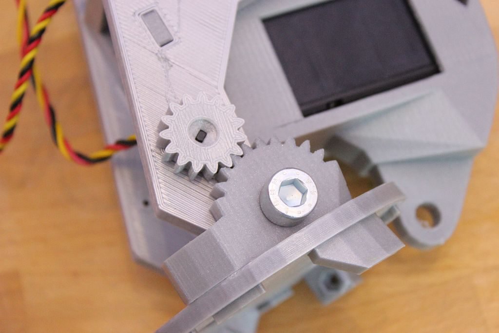
The Elbowshaftgear and the Robcap are glued together and then mounted on the bicep with a 8mm bolt.
My
potentiometer fits nicely in the square hole. It doesn’t need any screws now,
but maybe I will add them later. On the potentiometer the Gearpotentio is
mounted. The Gearholder then is slided over the gear to prevent is from sliding
off.
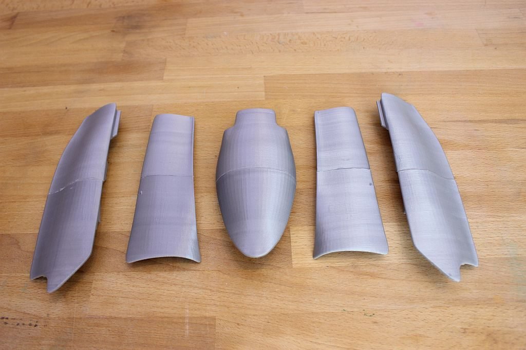
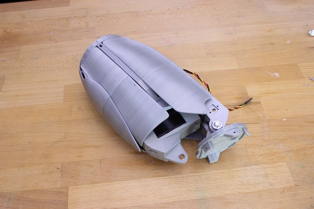
The last step in this assembly is to glue all covers together and mount them on the bicep. It’s looks a lot cooler with the covers on. I needed to file some parts because it didn’t fit.
In the
next episode I am going to build the lower arm and will connect the arm to the
shoulders part of the inMoov. If you have questions or comments, please let me
know. inMoov is designed by Gaël Langevin so make sure you visit is website at https://inmoov.fr
After the crash of my inMoov robot it took a lot of work to put it back together. To prevent a crash again I decided buy a stable speaker stand for big speakers. To make it fit it was necessary to design a special block to connect the upper body of the inMoov robot to the 35 mm pipe of the speaker stand.
My speaker stand is from the brand Innox, but there are several brands offering the same product. For example: Speaker stand on Amazon.
Wow. Time flies when you having fun. This website is about my the things I build in my free time. Last 2 years where very intense at work and in my private life. Now I decided to work less, to put more time in building robots and at first finish my inMoov robot.
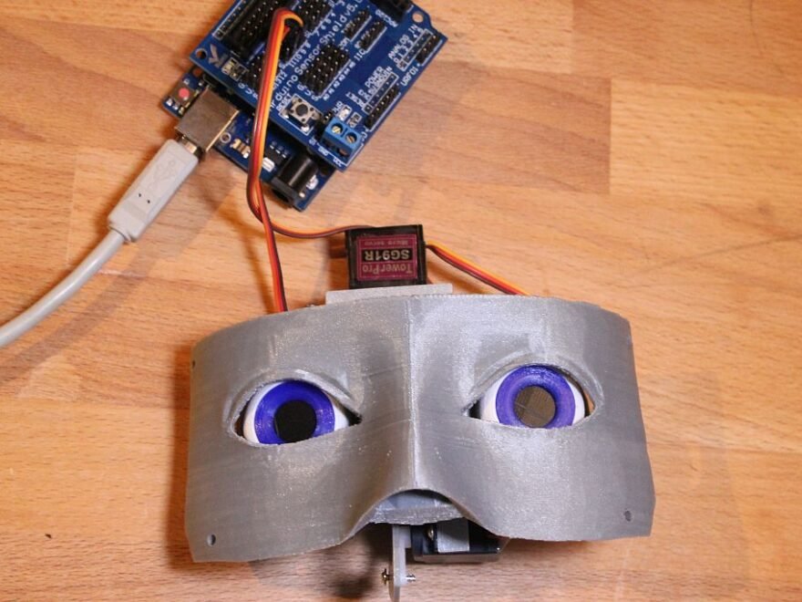
After the crash on the floor and all the broken pieces the robot in the same state where I left off before my last post. The first thing to do was finishing the Eye Mechanism of my inMoov robot.
In the designs of the inMoov robot (www.inMoov.fr) you can add small camera’s. In this stage I don’t want to use these yet, so I will use an round piece of 3D printed plastic to cover the hole in the eye. I also want to keep the inMoov robot as robot like as it can be at the moment. So I don’t bother to make the eye as realistic as it can be.
I made a video of the build on my YouTube channel.
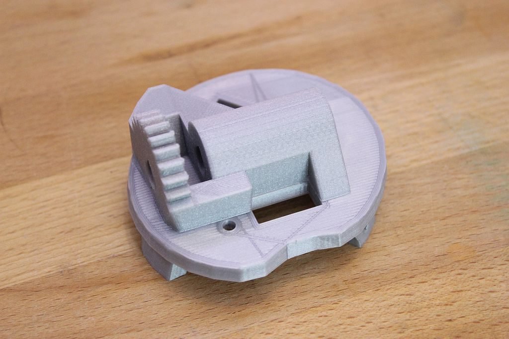
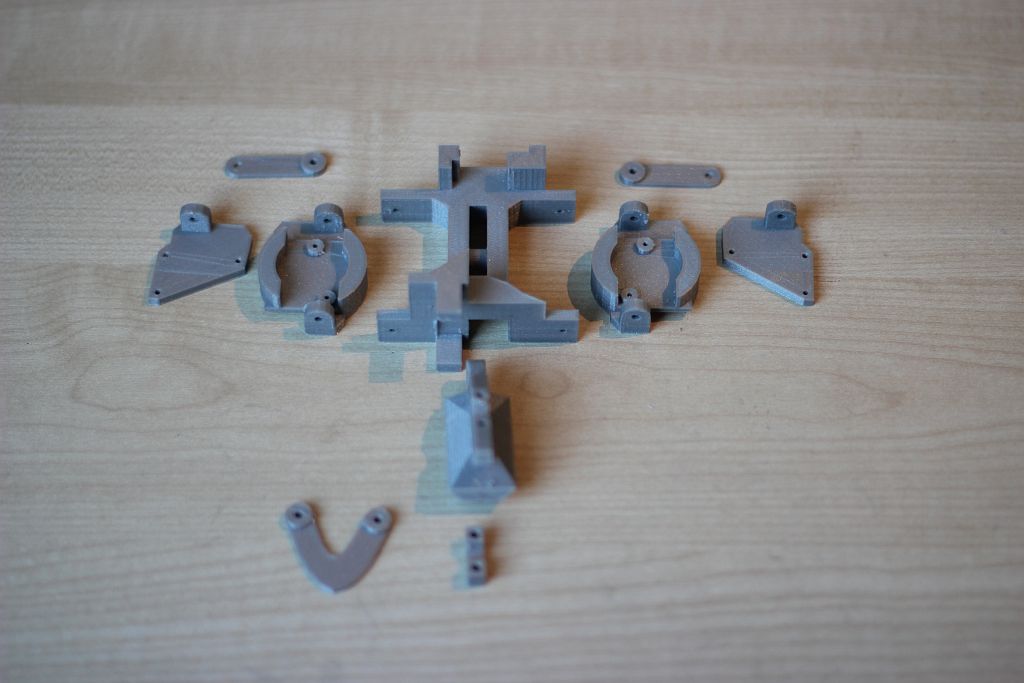
The Eye mechanism has some small parts.On the picture below you can see the standard parts.
The parts fitted nicely. The only thing that not fit directly was the EyeHingeCurve. Probably because I used an other servo than Gael Langevin did in his design. I had to adjust the hinge with a knife 😉
The final eye Mechanism.
In the Youtube video I used a small test code in arduino to move the eyes. You can use this code to test your own servo. In this example the servo’s are connected to a Arduino Mega on pin 22 and 24. Please change the value’s to your needs.
/* Based on the Sweep example
 by BARRAGAN <http://barraganstudio.com>
 This example code is in the public domain.

modified 8 Nov 2013
 by Scott Fitzgerald
 http://arduino.cc/en/Tutorial/Sweep

Modified to control Eye mechanism inMoov robot (With Arduino Mega)
 https://swanrobotics.com
 */

#include <Servo.h>

Servo horServo; // Horizontal servo (left tot right)
 Servo verServo; // Vertical servo (Up and down)

// Change these settings to your own setup and preferences.
 int horServoPin = 22;
 int horMaxLeft = 60; // Maximum servo position Left
 int horMid = 90; // Middle servo position horizontal
 int horMaxRight = 120; // Maximum servo position Right
 int horStep = 1; // Step size for position horizontal

int verServoPin = 24;
 int verMaxUp = 45; // Maximum servo position Up
 int verMid = 65; // Middle servo position vertical
 int verMaxDown = 95; // Maximum servo position Down
 int verStep = 1; // Step size for position vertical

int delaySpeed = 500; // time between the movement
 int pos = 0; // variable to store the servo position
 int positionwait = 5; // variable to wait for the servo to reach the position

void setup()
 {
 horServo.attach(22); // attaches the servo on horzontal pin
 verServo.attach(24); // attaches the servo on vertical pin

horServo.write(horMid); // Put horizontal servo in neutral position
 verServo.write(verMid); // Put vertical servo in neutral position
 }

void loop()
 {

// Look right
 for(pos = horMid; pos <= horMaxRight; pos += horStep)
 {
 horServo.write(pos);
 delay(positionwait);
 }
 delay(delaySpeed);

// Look left
 for(pos = horMaxRight; pos>=horMaxLeft; pos-=horStep)
 {
 horServo.write(pos);
 delay(positionwait);
 }
 delay(delaySpeed);

// Look neutral
 for(pos = horMaxLeft; pos<=horMid; pos+=horStep)
 {
 horServo.write(pos);
 delay(positionwait);
 }
 delay(delaySpeed);

// Look Up
 for(pos = verMid; pos <= verMaxDown; pos += verStep)
 {
 verServo.write(pos);
 delay(positionwait);
 }
 delay(delaySpeed);

// Look down
 for(pos = verMaxDown; pos>=verMaxUp; pos-=verStep)
 {
 verServo.write(pos);
 delay(positionwait);
 }
 delay(delaySpeed);

//Look neutral
 for(pos = verMaxUp; pos <= verMid; pos += verStep)
 {
 verServo.write(pos);
 delay(positionwait);
 }
 delay(delaySpeed);
 }
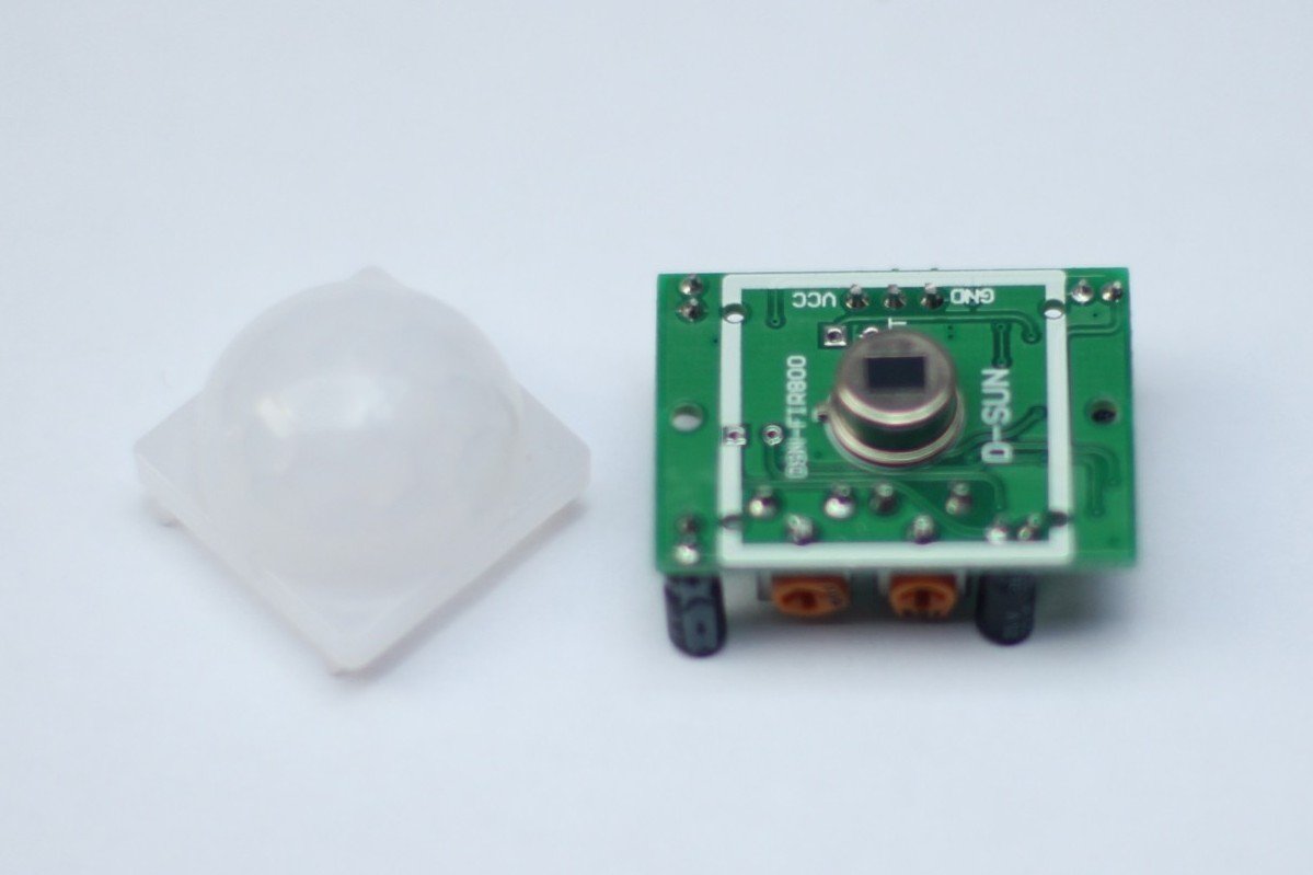
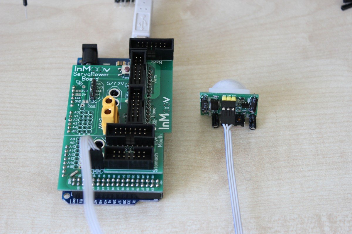
The inMoov will be fitted with a PIR module. This Passive Infrared Sensor measures the infrared light radiates from object it’s pointed at. A PIR module can be used to detect if somebody is in front of the inMoov robot. I am thinking of using the sensor to power up the inmoov robot so it can reduce power when nobody is in front of it.
I used a simple module what can be purchased on several web shops around the world.
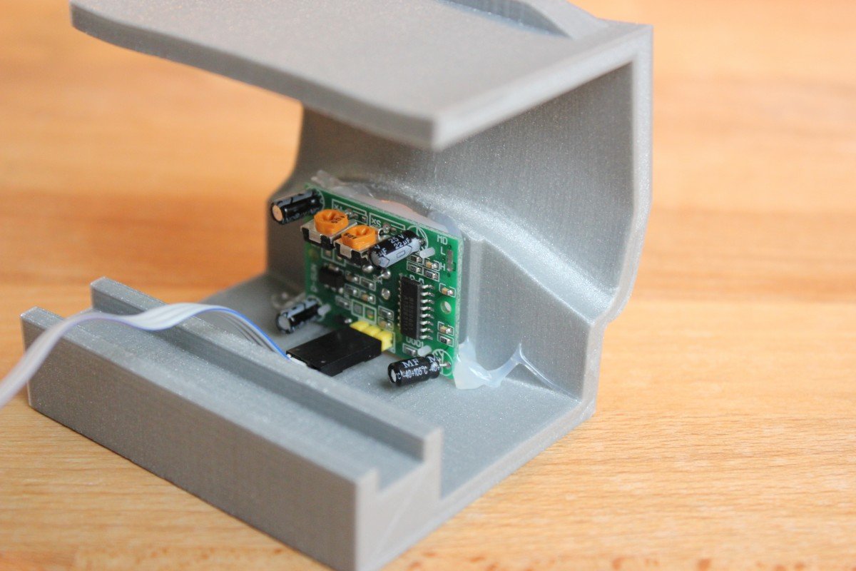
This module has a footprint of 32,5 mm x 24,5 mm x 25 mm and has three pins. One pin is for 5V power and one ground pin. The third pin is the data pin and is High when motion is detected. The modules as two potentiometers. The left potentiometer is for the sensitivity and the right is for the duration the pin should be high after motion is detected. The sensitivity is depending on your situation. For the duration I used the shortest setting because I don’t expect I to miss this trigger.
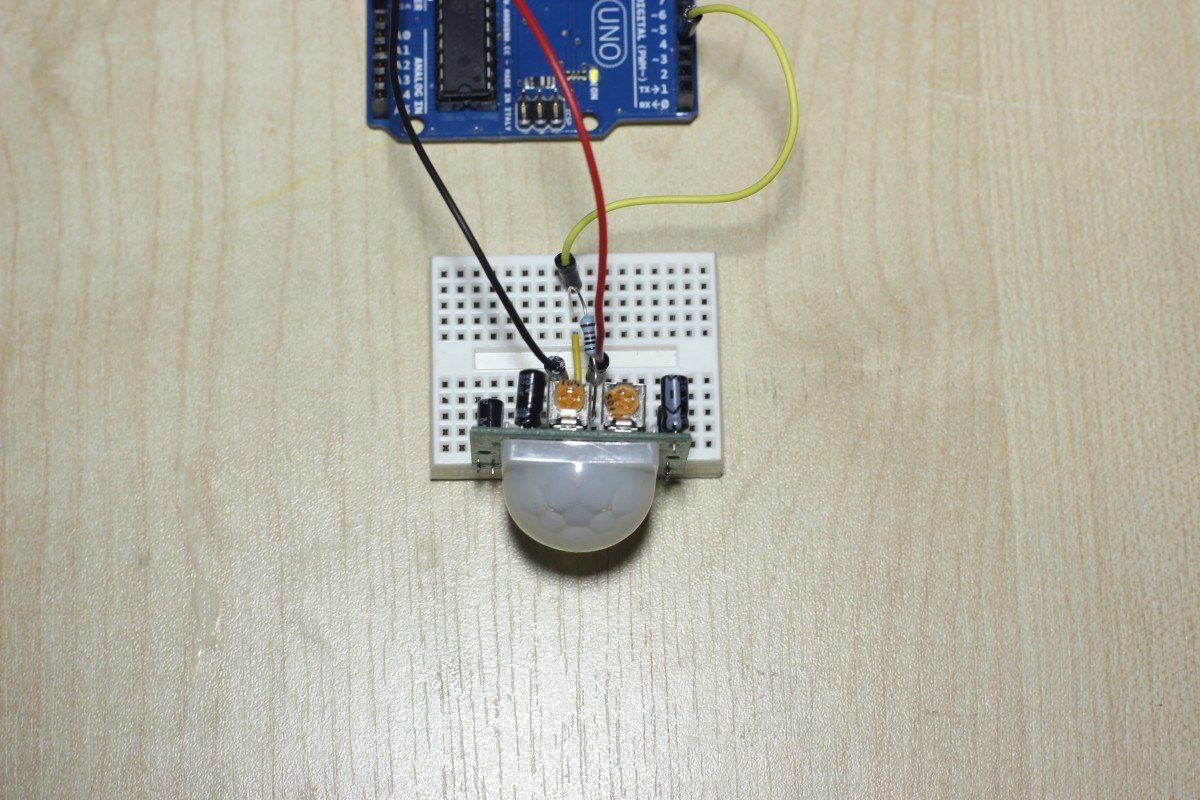
The picture below shows how the PIR module is connected with an Arduino. I used this to test the module.
The PIR module has it’s own connection on the Nervo Board. It’s located next to pin A15, D44 and D46. I made a ribbon cable to connect the sensor to the board. The pins on the PIR module and the Nervo Board are not in the same order. I needed to swap the vcc pin and the signal pin on one end as you can see in the picture below.
To test the PIR module and it connections I used a little piece of Arduino code. The signal pin of the PIR module is connected to pin 23 on the Nervo Board. The code is checking every second if motion is detected and prints the results in the Serial Monitor.
[code lang=”cpp”]
/*
* This is an example of how to use a PIR sensor with an Arduino.
* www.swanrobotics.com
*/
// Define pin 23 as input for the sensor
#define MOTION_PIN 23
// Initilize serial link for debugging
Serial.begin(9600);
delay(1000); // 1 second delay to open the serial monitor after uploading
Serial.println (“Start”);
}
I have printed the MiddleChest+PIRV1 part which has a space for the PIR sensor. This part is already mounted on my inMoov so I only had to hotglue the PIR module in place.
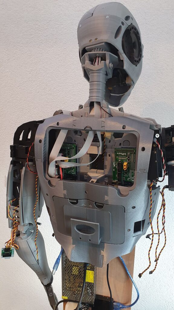
This picture below shows the final result in the chest of the inMoov robot
To show you how the PIR is mounted in the inMoov robot I made a small video.
All this was not possible by the creator of the inMoov robot. Please visit his website www.inmoov.fr
The summertime was not the best time to work on my inMoov robot, because of outdoor activities. But now it is getting cold and the Dutch weather is keeping me inside. It is time to moving forward again.
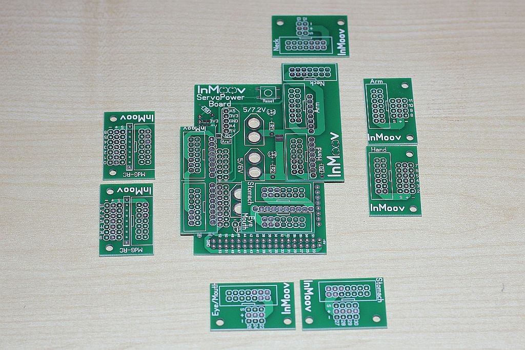
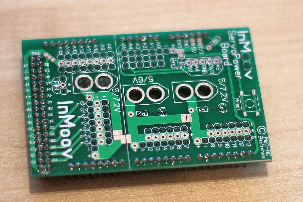
I ordered the Nervo Boards from the www.inMoov.fr website. I first ordered one set, because I wanted to see what the quality was. This was what I received.
I was happy with the quality so I ordered the second set also. First I had to figure out how the all boards supposed to fit together. For now I don’t want to use the finger sensors, but they are on the left side on the picture below.
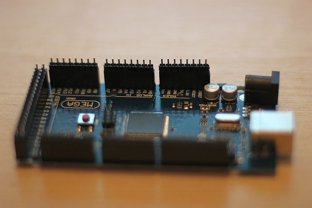
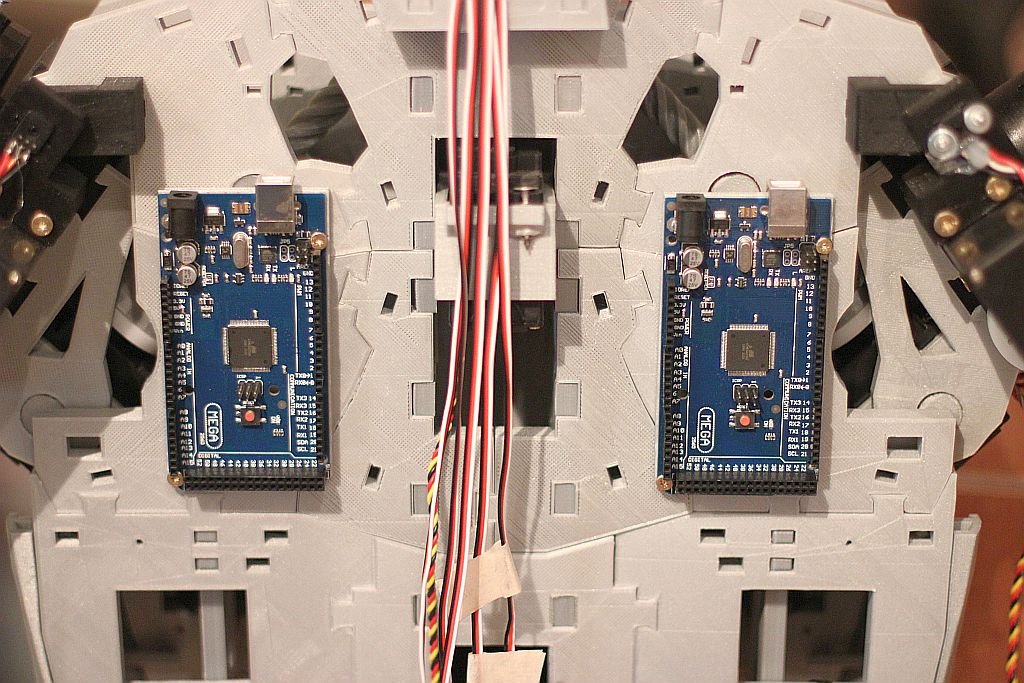
At first I took an Arduino Mega compatible board (Funduino) and inserted the pins needed for the Nervo Board. This is done to be sure that the pins are straight and on the right position. Beware: not all the pins on the Arduino Mega board are used, so leave those position empty.
Next I fitted the main Nervo Board over the pins on the Arduino Mega. The pins 8 till 13 didn’t fit perfectly. I don’t know of this was caused by the Nervo board or the Funduino. I had to lift one side up to bring the pin closer to the hole.
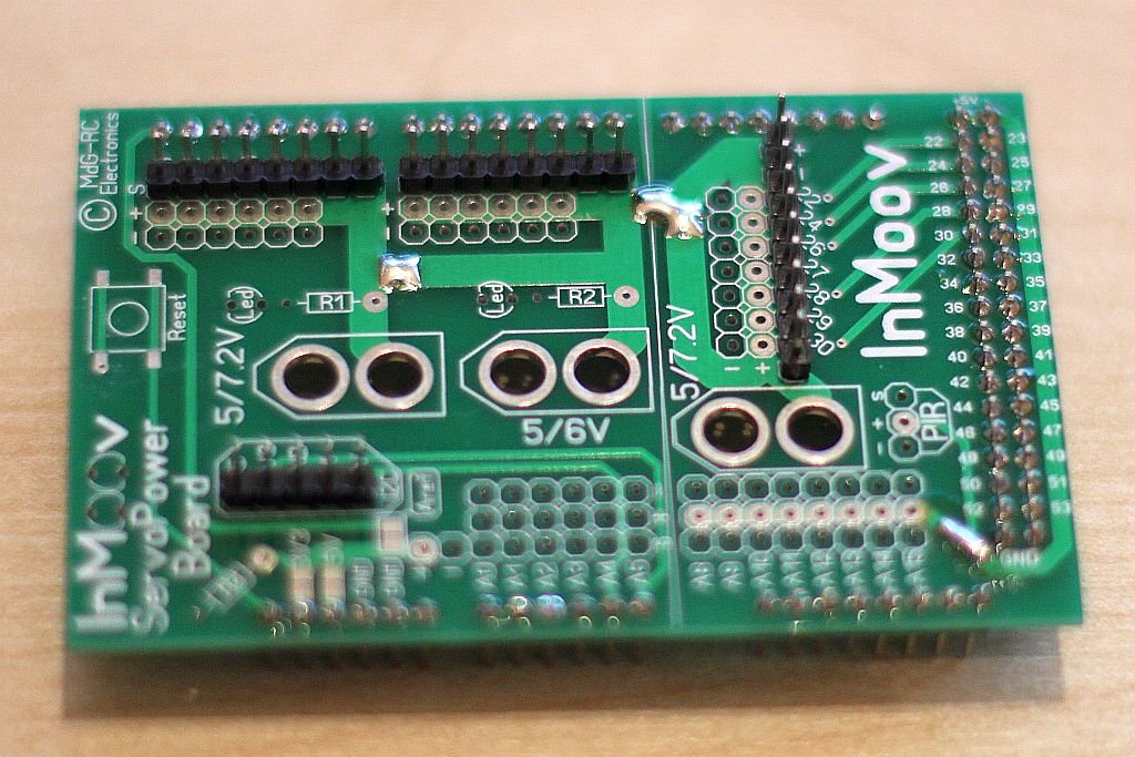
I soldered all together.
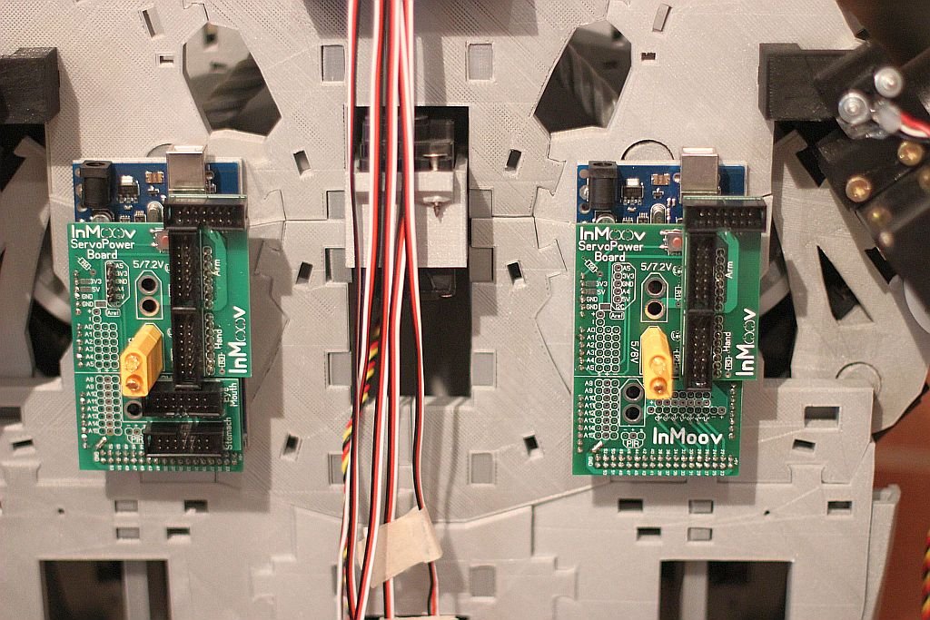
My inMoov will use the same Voltage for all the servos, so I soldered the 3 connections on the top side of the board. The solder did stick very well on the pads at bottom right on the picture. A little piece of wire was needed to make a solid connection.
I removed the head and neck pins from the main board, because I was afraid to burn the headers on the top board. I was easier to solder the pins on the top breakout board first and then solder the 12 pin connectors. Now it was easy to solder the breakout board on the Nervo main board.
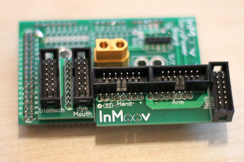
After an evening of soldering the result is very nice. The right board doesn’t have the neck and Stomach breakout board on it. You can use an Arduino Uno instead of an Arduino Mega. You never can have enough io. 😉
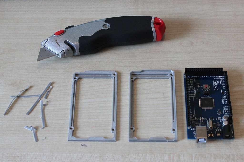
To mount the Nervo Board assemblies on my inMoov robot I printed a Mount from Thingiverse. [http://www.thingiverse.com/thing:30270]. It didn’t fit. I remove the rim around the board because I didn’t want to print another one.
I used two 3 x 16 mm screws to mount the assemblies on the back of the inMoov. There is not a dedicated spot for it, so I looked at a spot where the two screws would fit.
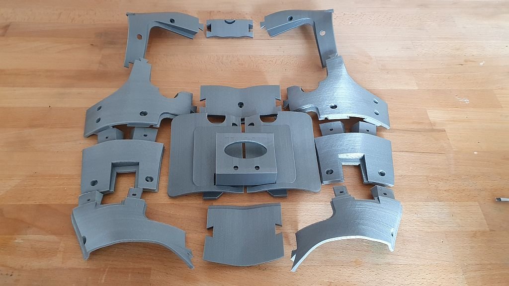
The world is unfair. My Ultimaker printer had to do more then 70 hours of printing and it took me only 1 hour to put the parts on the inMoov robot. 😉 Below you can see all the parts from the Chest.
From left to right and from top to bottom you can see the following parts:
ChestTopAttachV1 (right and left part)
ChestTopV1 (right and left part)
SideRibsCoverV1 (right and left part)
ChestRightV1
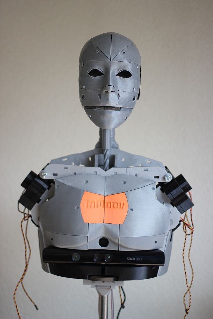
InMrightV1HollowV1 (orange)
InMleftV1HollowV1 (orange)
ChestLeftV1
BottomChestV1(right and left part)
MiddleChest+PIRV1
UnderKinectV1 (right and left part in black)
I am very happy with the results of these prints and they fit really well. The easiest way to mount the chestparts is starting with the ChestRight and ChestLeft together with the InMrightV1Hollow and InMleftHollow. After this you can mount the MiddleChest+PIR and the Kinect. The Kinect is mounted with the UnderKinect parts. I had to push it in with a little bit force to fit it together. I think this was caused by some warping of the prints.
The inMoov robot gets a PIR sensor to react on people moving by. This is not done yet so you can see a nice hole where the PIR sensor should.
Make sure you check the website from Gael Langevin at www.inmoov.fr.
Because of a holiday in Turkey I could not print for one week and wasn’t able to share the results with you.
The picture shows a lot of parts. From left to right and from top to bottom:
robpart3V3
robpart4V3
lowarmsideV1_square
rotawrist3V2
rotawrist2 (black part)
PivPotholderV21b (two black parts)
rotawrist1V3
cableholderwristV4
WristGearsV4 (3 gears)
PivPotentioV3 (4 black parts)
servo-pulleyX5
I did redo the lowarmsideV1, PivPotentioV3 and the PivPotholderV21 because I used the original one at frist and used a Dremel to make it fit. The potentiometers fit great is this new design so I made four of them.
Be sure you check the website from Gael Langevin at www.inmoov.fr.
Manage Consent
To provide the best experiences, we use technologies like cookies to store and/or access device information. Consenting to these technologies will allow us to process data such as browsing behavior or unique IDs on this site. Not consenting or withdrawing consent, may adversely affect certain features and functions.
Functional
Always active
The technical storage or access is strictly necessary for the legitimate purpose of enabling the use of a specific service explicitly requested by the subscriber or user, or for the sole purpose of carrying out the transmission of a communication over an electronic communications network.
Preferences
The technical storage or access is necessary for the legitimate purpose of storing preferences that are not requested by the subscriber or user.
Statistics
The technical storage or access that is used exclusively for statistical purposes.The technical storage or access that is used exclusively for anonymous statistical purposes. Without a subpoena, voluntary compliance on the part of your Internet Service Provider, or additional records from a third party, information stored or retrieved for this purpose alone cannot usually be used to identify you.
Marketing
The technical storage or access is required to create user profiles to send advertising, or to track the user on a website or across several websites for similar marketing purposes.


 .
.