Tag: Arduino

  • Levelconverter

    Levelconverter

    In my last article, I wrote about using an MD04 motor driver for my motors. In the example, I used an Arduino Uno to test the motor drivers and made the code work. I want to use the Teensy 4.1 in my robot because of the board’s multiple serial connections and its higher speed. The Teensy runs on 3.3 Volt instead of the 5V Arduino uses. I could not find the voltage level for the I2C wiring in the documentation. According to the manual, the serial communication and the analog input use 5V, so I assume the SCL and SDA are the same.

    To overcome the voltage differences, I used a level converter. A level converter is a small board with a low and a high-level side. A MOSFET and other components on this board compensate for the voltage difference between the two sides. Connect the low-level side (LV) to the Teensy and the high-level side (HV) to the MD03. The image below shows how I wired the Teensy, the motor driver, and the level converter.

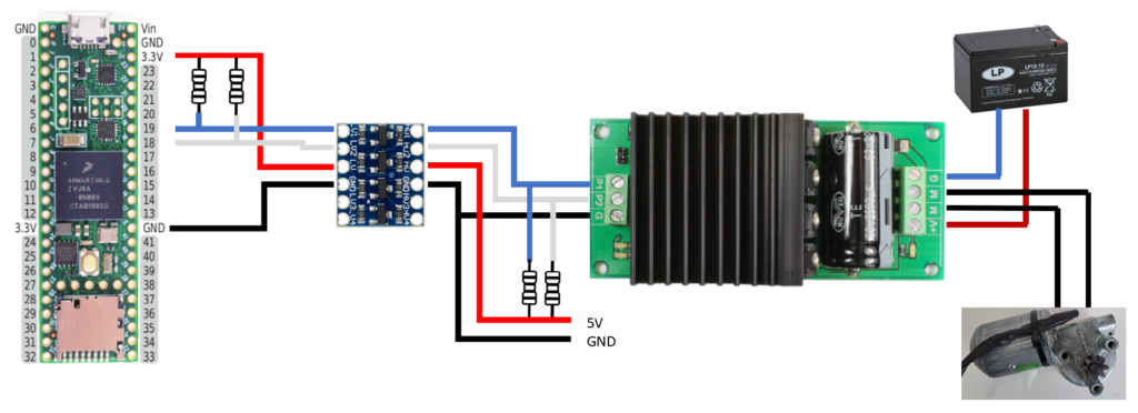
    I used a USB breakout board to provide the 5 volts to the high side of the level converter. The low side of the level converter gets its power from the Teensy. I used two pull-up resistors on both sides of the level converter (10K). Technical, the connections remained the same. We used the standard I2C pins, so the software stayed the same. You can use the code example from the previous article.

    Supplies

    Level Converter
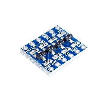
    Buy at AliExpress
    Buy at Amazon
    Make sure you get the Bi-Directional version to use it with I2C.

  • Eye Mechanism inMoov robot

    Eye Mechanism inMoov robot

    Wow. Time flies when you having fun. This website is about my the things I build in my free time. Last 2 years where very intense at work and in my private life. Now I decided to work less, to put more time in building robots and at first finish my inMoov robot.

    After the crash on the floor and all the broken pieces the robot in the same state where I left off before my last post. The first thing to do was finishing the Eye Mechanism of my inMoov robot.

    In the designs of the inMoov robot (www.inMoov.fr) you can add small camera’s. In this stage I don’t want to use these yet, so I will use an round piece of 3D printed plastic to cover the hole in the eye. I also want to keep the inMoov robot as robot like as it can be at the moment. So I don’t bother to make the eye as realistic as it can be.

    I made a video of the build on my YouTube channel.

    The Eye mechanism has some small parts.On the picture below you can see the standard parts.

    The parts fitted nicely. The only thing that not fit directly was the EyeHingeCurve. Probably because I used an other servo than Gael Langevin did in his design. I had to adjust the hinge with a knife 😉

    The final eye Mechanism.

    In the Youtube video I used a small test code in arduino to move the eyes. You can use this code to test your own servo. In this example the servo’s are connected to a Arduino Mega on pin 22 and 24. Please change the value’s to your needs.

    /* Based on the Sweep example
     by BARRAGAN <http://barraganstudio.com>
     This example code is in the public domain.
    
    modified 8 Nov 2013
     by Scott Fitzgerald
     http://arduino.cc/en/Tutorial/Sweep
    
    Modified to control Eye mechanism inMoov robot (With Arduino Mega)
     https://swanrobotics.com
     */
    
    #include <Servo.h>
    
    Servo horServo; // Horizontal servo (left tot right)
     Servo verServo; // Vertical servo (Up and down)
    
    // Change these settings to your own setup and preferences.
     int horServoPin = 22;
     int horMaxLeft = 60; // Maximum servo position Left
     int horMid = 90; // Middle servo position horizontal
     int horMaxRight = 120; // Maximum servo position Right
     int horStep = 1; // Step size for position horizontal
    
    int verServoPin = 24;
     int verMaxUp = 45; // Maximum servo position Up
     int verMid = 65; // Middle servo position vertical
     int verMaxDown = 95; // Maximum servo position Down
     int verStep = 1; // Step size for position vertical
    
    int delaySpeed = 500; // time between the movement
     int pos = 0; // variable to store the servo position
     int positionwait = 5; // variable to wait for the servo to reach the position
    
    void setup()
     {
     horServo.attach(22); // attaches the servo on horzontal pin
     verServo.attach(24); // attaches the servo on vertical pin
    
    horServo.write(horMid); // Put horizontal servo in neutral position
     verServo.write(verMid); // Put vertical servo in neutral position
     }
    
    void loop()
     {
    
    // Look right
     for(pos = horMid; pos <= horMaxRight; pos += horStep)
     {
     horServo.write(pos);
     delay(positionwait);
     }
     delay(delaySpeed);
    
    // Look left
     for(pos = horMaxRight; pos>=horMaxLeft; pos-=horStep)
     {
     horServo.write(pos);
     delay(positionwait);
     }
     delay(delaySpeed);
    
    // Look neutral
     for(pos = horMaxLeft; pos<=horMid; pos+=horStep)
     {
     horServo.write(pos);
     delay(positionwait);
     }
     delay(delaySpeed);
    
    // Look Up
     for(pos = verMid; pos <= verMaxDown; pos += verStep)
     {
     verServo.write(pos);
     delay(positionwait);
     }
     delay(delaySpeed);
    
    // Look down
     for(pos = verMaxDown; pos>=verMaxUp; pos-=verStep)
     {
     verServo.write(pos);
     delay(positionwait);
     }
     delay(delaySpeed);
    
    //Look neutral
     for(pos = verMaxUp; pos <= verMid; pos += verStep)
     {
     verServo.write(pos);
     delay(positionwait);
     }
     delay(delaySpeed);
     }


  • Nervo Boards

    Nervo Boards

    The summertime was not the best time to work on my inMoov robot, because of outdoor activities. But now it is getting cold and the Dutch weather is keeping me inside. It is time to moving forward again.

    I ordered the Nervo Boards from the www.inMoov.fr website. I first ordered one set, because I wanted to see what the quality was. This was what I received.

    01inmoovprints

    I was happy with the quality so I ordered the second set also. First I had to figure out how the all boards supposed to fit together. For now I don’t want to use the finger sensors, but they are on the left side on the picture below.

    02Printssorted

    At first I took an Arduino Mega compatible board (Funduino) and inserted the pins needed for the Nervo Board. This is done to be sure that the pins are straight and on the right position. Beware: not all the pins on the Arduino Mega board are used, so leave those position empty.

    03Pins

    Next I fitted the main Nervo Board over the pins on the Arduino Mega. The pins 8 till 13 didn’t fit perfectly. I don’t know of this was caused by the Nervo board or the Funduino. I had to lift one side up to bring the pin closer to the hole.

    04Pins with board

    I soldered all together.

    05pinssolder

    06solderbottom

    My inMoov will use the same Voltage for all the servos, so I soldered the 3 connections on the top side of the board. The solder did stick very well on the pads at bottom right on the picture. A little piece of wire was needed to make a solid connection.

    07bridge

    I removed the head and neck pins from the main board, because I was afraid to burn the headers on the top board. I was easier to solder the pins on the top breakout board first and then solder the 12 pin connectors. Now it was easy to solder the breakout board on the Nervo main board.

    08pinsupper 09upperboards
    After an evening of soldering the result is very nice. The right board doesn’t have the neck and Stomach breakout board on it. You can use an Arduino Uno instead of an Arduino Mega. You never can have enough io. 😉

    10allboard

    To mount the Nervo Board assemblies on my inMoov robot I printed a Mount from Thingiverse. [http://www.thingiverse.com/thing:30270]. It didn’t fit. I remove the rim around the board because I didn’t want to print another one.

    11megamount

    I used two 3 x 16 mm screws to mount the assemblies on the back of the inMoov. There is not a dedicated spot for it, so I looked at a spot where the two screws would fit.

    12oninmoov13With board


  • GP2D12 Project added

    On the last day of the year I managed to add a new project after a long time. This little project is all
    about the GP2D12 sensor. With this sensor you can measure the distance to an object in front of your
    robot. You can find the project https://swanrobotics.com/projects/gp2d12_project/

  • Update on the Wireless Arduino Project

    I got a remark from Johan because he found out that you have to disconnect the APC220 before uploading the sketch. I have added it to project page.  https://swanrobotics.com/Wireless_Arduino

  • New project with Arduino

    Today I published a small project to measure voltage with an Arduino. This has great use for checking the battery of your mobile robot.
    See https://swanrobotics.com/projects/voltagedivider/ for the article.

  • Published Article on Fritzing.org

    The Arduino wireless APC220 project is now published on http://Fritzing.org to share it to a broader public. See http://fritzing.org/projects/wireless-arduino-with-apc220.