The first thing to do for my A1 robot is to control the motors. I wanted to use MD03 motor drivers from Devantech. I had used them before on the same robot. You cannot buy them anymore because Devantech has a newer motor driver available. I had it all working fine, but then I made a mistake. A 24V power lead connected the 5V circuit because I forgot to disconnect the battery connector when changing the configuration. I had to buy two new MD04 drivers. Ouch. I got mine from www.robotshop.com.
MD04
These drivers look the same, but the power of the control circuit comes from the motor circuit. Powering the board this way is a disadvantage because, with the MD03 configuration, I routed the power wires through the emergency stop. Cutting the power stops the motors immediately. I can’t do the same thing with the power of the drive side because the switch can not handle the current flowing through.
In my design, I want to control the MD04 motor drivers through I2C. It’s easier to use PWM, but by using I2C, I can read data from the MD04. The data I want to use is the current flowing through the motor and the temperature of the driver. If the current is too high, we can determine if the motor is struggling or stalling. You can also get the version of the software of the MD04 motor driver. To set up an I2C connection, you need to configure the MD04 with the software from Deventac en set the communication to I2C. A useful source about the I2C bus is: I2C Bus (i2c-bus.org)
Connect to an Arduino
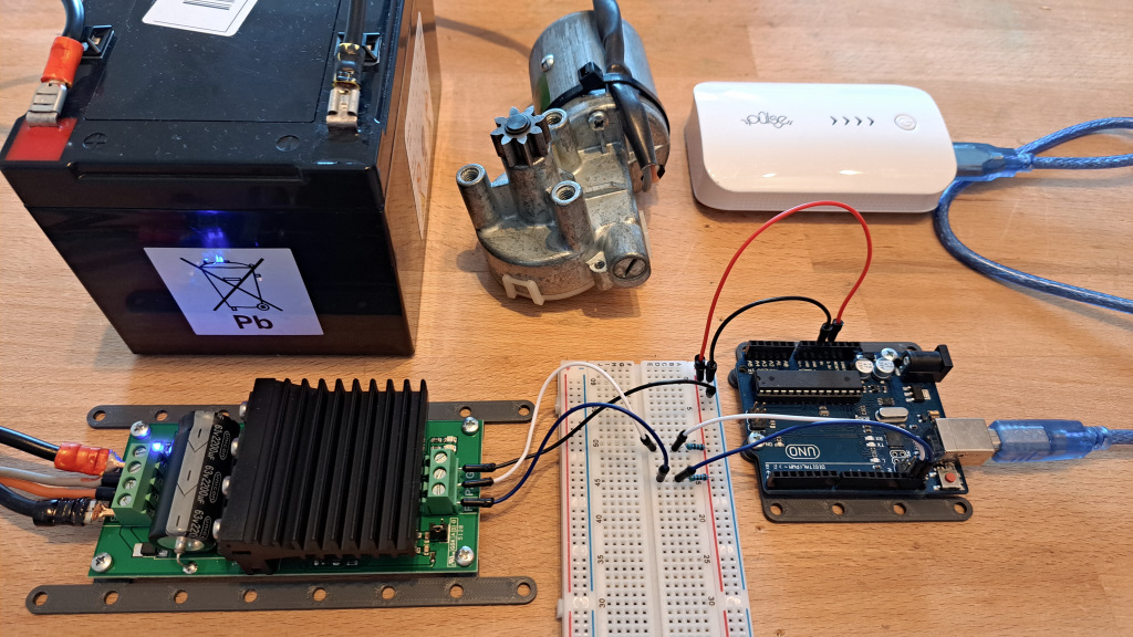
My robot has two MD04 drivers, and with I2C, we can control them both with two pins. To make this work, I connected the boards with USB to my computer and configured the boards with the software from Devantech. MD04 (robot-electronics.co.uk) It’s a simple program, and you can select the address for the motor drivers.
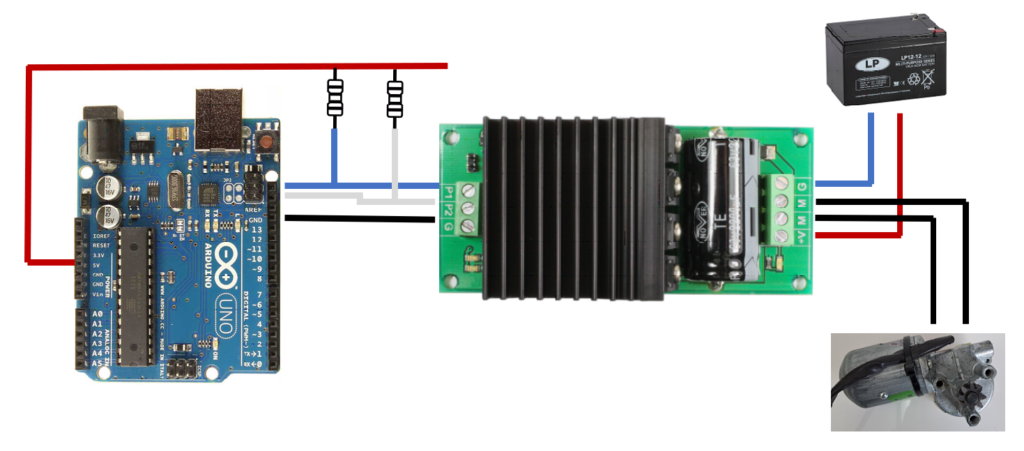
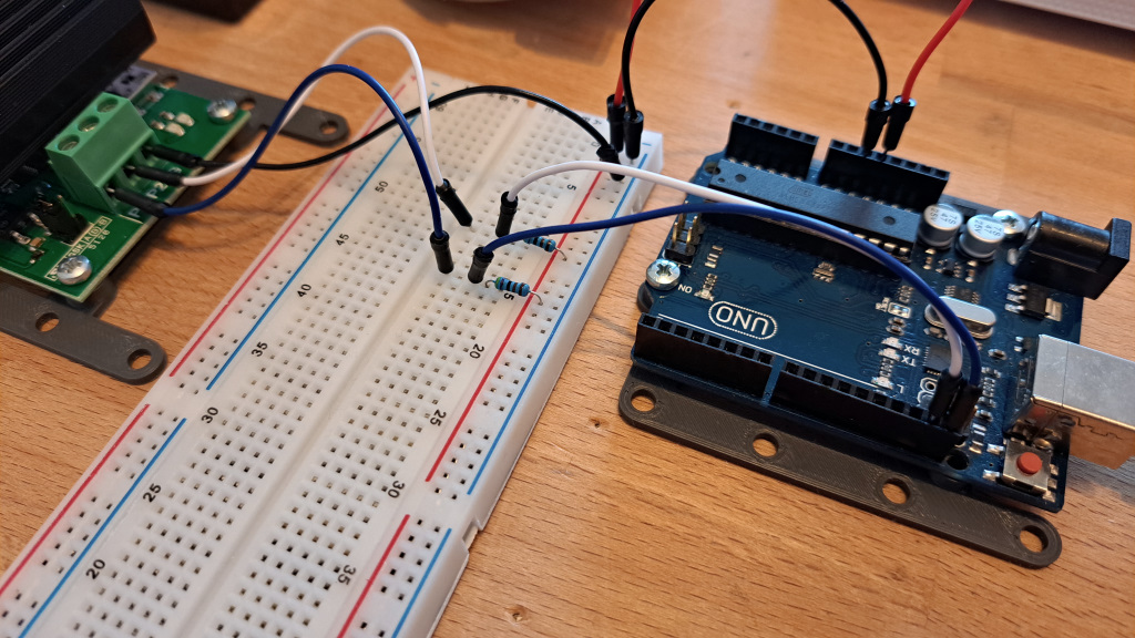
The MD04 only uses three wires. P1 is the SCL, P2 is the SDA, and a GND wire is needed. On the Arduino Uno, the SCL is GPIO19 and SDA is GPIO18. I2C also needs two pull-up resistors (I used 4.7k) on the lines to prevent data loss. The rest of the schematic is reasonably straightforward. Internally on the MD04 board, the ground is connected. Connecting the ground poles from the 24V and 5V sources is not desirable to prevent ground loops.
Arduino Code
For the program, I started with the example: Arduino Examples (robot-electronics.co.uk) This example also used a display; I only needed the part to control the motors, so I changed the code example from James Henderson to a simpler version. The purpose is to make a loop of spinning a motor to half the speed and slowing down to a halt. At the same time, the code needs to read the information from the MD04 and send them to the serial connection. The code below is also available at GitHub: https://github.com/SwanRobotics/arduino-md04
/*
 * From www.swanrobotics.com
 *
 * Code example for an MD04 motor driver from Robot Electronics for Arduino
 * https://www.robot-electronics.co.uk/md04.html
 *
 * In a loop, the code spins up the motor to maximum speed and slows it down to a hold.
 * Then change the direction and goes to maximum speed, and hold again.
 * It uses the I2C protocol from the Wire library.
 *
 * To connect the MD04 motor driver, for example, an Arduino Uno with the following connections:
 *  MD04      Arduino Uno
 *  P1    <=> D19 (SCL)
 *  P2    <=> D18 (SDA)
 *  G     <=> GND
 *
 * The original code by:
 * James Henderson 2012
 * https://www.robot-electronics.co.uk/htm/arduino_examples.htm#MD03%2050V%2020A%20Motor%20Driver
 */

#include <Wire.h>

#define ADDRESS             0x58                    // Address of MD03
#define SOFTREG             0x07                    // Byte to read software
#define CMDBYTE             0x00                    // Command byte
#define SPEEDBYTE           0x02                    // Byte to write to speed register
#define TEMPREG             0x04                    // Byte to read temperature
#define CURRENTREG          0x05                    // Byte to read motor current

byte direct = 1;                                    // Stores what direction the motor should run in

void setup(){
  Serial.begin(19200);                              // Start Serial connection
  delay(100);

  Wire.begin();                                     // Start I2C connection
  delay(100);

  Serial.print("Software version MD04: ");          // Print Software version from MD04
  Serial.println(getData(SOFTREG));
}

void loop(){
  for(int i = 0; i < 250; i=i+10){
    sendData(SPEEDBYTE, i);             // Sets speed to i
    sendData(CMDBYTE, direct);          // Sets motor to direct, a value of 1 runs the motor forward and 2 runs backward
    showData(direct,i);                 // Call function to print data to Serial
    delay(100);                         // Wait 0,1 second to send the next speed value
  }
  delay(100);
  for(int i = 250; i > 10; i=i-10){
    sendData(SPEEDBYTE, i);             // Sets speed to i
    sendData(CMDBYTE, direct);          // Sets motor to direct, a value of 1 runs the motor forward and 2 runs backward
    showData(direct,i);                 // Call function to print data to Serial
    delay(100);                         // Wait 0,1 second to send the next speed value
  }
  if(direct == 1)                       // If loop that swaps value of direct between 1 and 2 each time through loop
    direct = 2;
  else
    direct = 1;
}

void showData(byte valdirection, byte valSpeed) {
    Serial.print("Direction: ");
    Serial.print(valdirection);         // Prints current direction (1 or 2)
    Serial.print(" - Speed: ");
    Serial.print(valSpeed);             // Prints current Speed (0-250) tot Serial

    byte current = getData(CURRENTREG); // Get current value (186 = 20 Amp) to Serial
    delay(10);
    Serial.print(" - Current: ");
    Serial.print(current);

    byte temp = getData(TEMPREG);       // Get surface temperature of the PCB in degrees centigrade.
    delay(10);
    Serial.print(" - Temperature: ");
    Serial.print(temp);

    Serial.println(".");                // Point at the end of the line and an Enter
}

byte getData(byte reg){                 // function for getting data from MD03
  Wire.beginTransmission(ADDRESS);
  Wire.write(reg);
  Wire.endTransmission();

  Wire.requestFrom(ADDRESS, 1);         // Requests byte from MD03
  while(Wire.available() < 1);          // Waits for byte to become available
  byte data = Wire.read();

  return(data);
}

void sendData(byte reg, byte val){      // Function for sending data to MD03
  Wire.beginTransmission(ADDRESS);      // Send data to MD03
    Wire.write(reg);                    // Command like Direction, Speed
    Wire.write(val);                    // Value for the command
  Wire.endTransmission();
}
Adresses?
The addresses for controlling the MD04 differ from what you expect because I2C uses the upper 7 bits for addressing. The extra bit is for telling the MD04 board to read return data. So if we configure the board with Address B0, we have to send 0x58 (hexadecimal) to the MD04.
Hexadecimal = B0
Binary = 1011 0000 (8 bits)
When discarding the last bit:
Binary = 1011 000 (7 bits)
Hex = 58
Receiving data
When reading data from the MD04, you must be aware that the current value is proportional to motor current, with 186 representing the 20A limit. The temperature value is the temperature from the PCB in degrees centigrade.
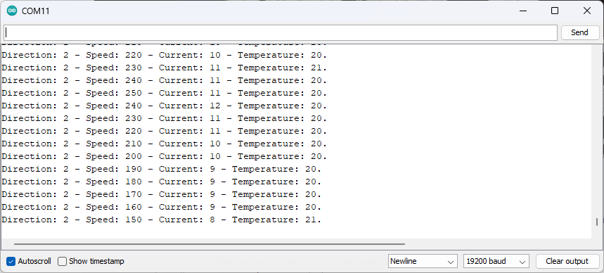
The output to Serial from the Arduino will show the Direction (1 or 2), and speed sent to the MD04. The Current and Temperature returned are received from the MD04.
Conclusion
Controlling a motor driver with an Arduino is straightforward, and the code is simple enough. You only have to be aware of the addresses used by I2C. You can use this information for your projects. See the code in action Motor driver MD04 with Arduino Uno – YouTube.