Tag: Build

  • ESP-Now Remote Control Test

    ESP-Now Remote Control Test

    To control a robot, I wanted to see if ESP-NOW, a communication method developed explicitly for the ESP family, would work. This project aims to determine whether ESP-NOW provides a reliable connection over a reasonable distance and whether ESP-NOW can send sufficient data back and forth.
    ESP-NOW makes it possible to set up different types of communication:

    • One-way communication
    • One master and multiple slaves
    • One slave and multiple masters
    • Two-way communication
    • Multiple-way communication (a network of ESP boards)

    In my example, I use the two-way communication protocol to build a remote control that can operate a robot. The robot must also send data back. If you want to read more about the possibilities and background of ESP-NOW, check out this excellent source of information:
    https://randomnerdtutorials.com/esp-now-esp32-arduino-ide/

    Setup

    My first test setup consists of the following components:

    Board 1

    • Joystick (Sends signal)
    • Prints the distance from the distance sensor via Serial

    Board 2

    • Servo (Uses X position from the joystick)
    • HC-SR04 distance sensor mounted on the servo
    • Prints the distance from the distance sensor via Serial

    The joystick on the master board controls the servo on the slave board. The distance sensor rotates along with the servo, and the measured distance is sent back to the master board. The setup is simple, and it gives a first impression of the speed and reliability of the ESP-NOW connection.

    BOM (Bill of Materials)

    In this project, I used:

    • DOIT ESP32 DEVKIT V1
    • ESP32S 38P/V4/Goouuu Expansion board
    • ESP32/V4/Goouuu Terminal Adapter Expansion board
    • Dual-axis XY Joystick Module
    • Tower Pro Micro Servo SG90
    • HC-SR04 Distance sensor
    • Level Converter board
    • Jumpwires
    • 3D printed parts (Optional)

    Of course, you can use different components if you want — no problem at all.

    Preparation

    To use ESP-NOW, you need to know the MAC addresses of the ESP boards. It is essential to send data to the correct board. You can find this easily by uploading the following code and reading the MAC address via the Serial Monitor in the Arduino IDE:

    #include "WiFi.h"
    
    void setup(){
      Serial.begin(115200);
      WiFi.mode(WIFI_MODE_STA);
      Serial.println(WiFi.macAddress());
    }
    
    void loop(){
    }

    Once uploaded, open the Serial Monitor and press the reset button on the DOIT board, and the MAC address will appear.

    Build

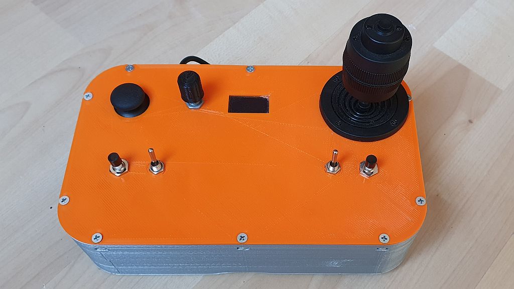
    Once we know the MAC addresses, we can start building the setup. I’m using parts from Evenblox to keep everything neatly together and make it easier to transport. You can find these parts and more information on https://www.evenblox.com. Also, check out this great 3D model for mounting your sensor: HCSR04 mount for SG90 servo by rjlew – Thingiverse

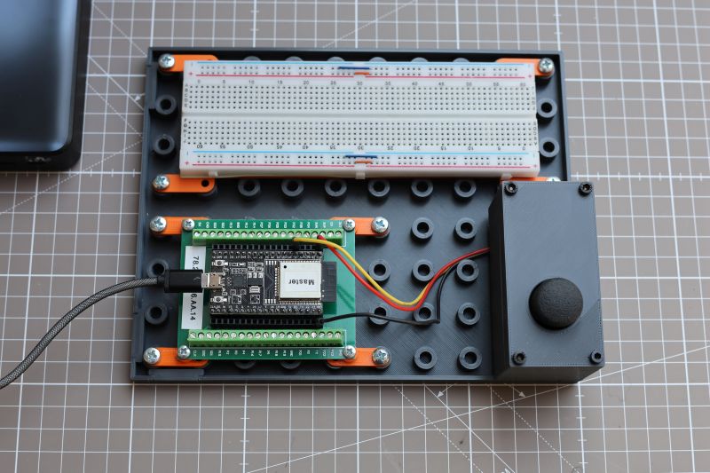
    Below you’ll find the schematic of board one (Master) and a photo of the breadboard setup:

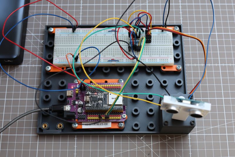
    Next is the schematic of board 2 (Slave) and a photo of its setup:

    I’m using the HC-SR04 sensor to measure distance. I’ve written an article about this before — check it out here: HC-SR04 Project – SwanRobotics.

    The servo and the HC-SR04 both run on 5V. The ESP32 operates at 3.3V, so a level converter is needed. There are HC-SR04 versions that support both 3.3V and 5V, but the one used in this project does not. For more information about level converters, check out Level Converter – SwanRobotics.

    Alternatively, you could use the HC-SR04P sensor, which supports both 3.3V and 5V directly.

    Code

    The code is available on GitHub. Remote_control_test_ESP-NOW

    You’ll need to update the MAC addresses in the code to make it work for your setup. The code handles several tasks:

    The remote sends a heartbeat every 200 ms. A heartbeat is essential when the system controls an actual robot. The robot checks for incoming data. If no data comes in, the servo returns to its middle position.
    The joystick value is sent to the robot, which reads it and converts it to a servo position.
    The sensor measures the distance and sends it back to the remote.
    The data from both ESP boards can be monitored via the Serial Monitor in the Arduino IDE, making it easy to test the connection in different locations.

    Once the code is uploaded, it should be possible to view the correct data.

    What’s Next

    This setup works well, and the ESP boards pass data smoothly. I want to test how far the boards can communicate in different environments (home, street, forest), so I’ll add a display to the remote control to show the connection status. That way, I can see when the signal is lost. The joystick is sensitive near the center position, so I plan to smooth that out in software.
  • Starting over

    Starting over

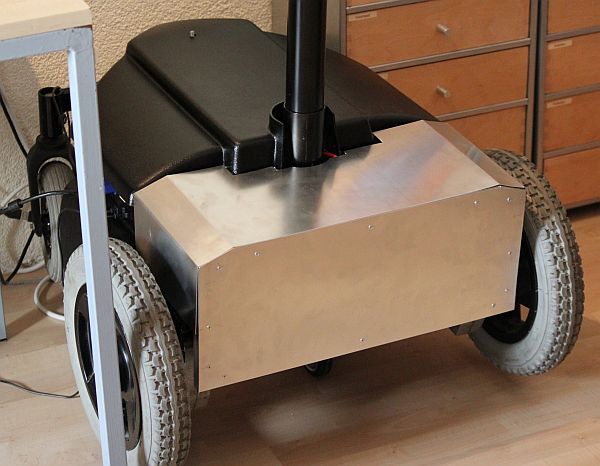
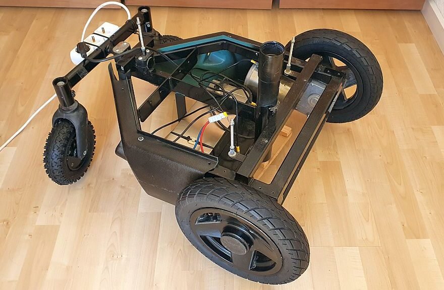
    My A1 robot is a robot based on a wheelchair. The robot’s purpose was to do telepresence. I built this thing 12 years ago and is collecting dust since then. I could not make it work at that time because of the lack of affordable technology, software possibilities, and my skillset.

    A lot has changed now. The widely available electronics and the amount of cheap computer power give much more functionality out of the box. I want the robot to be a platform capable of driving around autonomy and doing image-recognizing tasks like detecting garbage and faces.

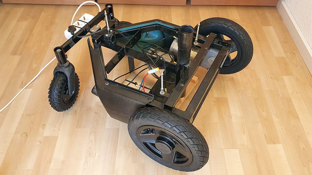
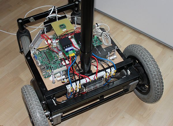
    The old electronics on this robot, like an Intel Mini ITX D945GSEJT and a servo driver, had to go. I ripped the electronics to make room for new components. I have already replaced the pulverized old tyers. The plan is to reuse the wheelchair base, motors, and motor drivers (MD03 from Devantech). The 24 Volt power supply is also staying for testing now. A Teensy 4.1 will do the low-level control, like handling the motor drivers and reading sensor data. This controller has many inputs and outputs and serial, SPI, CAN, and I2C ports.

    I haven’t decided what single-board computer I will use to do higher-level control. A prominent candidate is the NVIDIA Jetson Nano or better. It’s hard to get one because of a chip shortage. Another option is to use one or more Raspberry Pi boards and connect them with ethernet. The Teensy will use a serial connection to transfer data between a Raspberry Pi or the Jetson. This configuration makes it possible to build a modular system and allows swapping components when better components are available.

    The first task is to make the robot drive remote-controlled. I build a remote control for this with a Bluetooth module. There will also be a Bluetooth module connected to the Teensy on the robot. The motor drivers will be connected through I2C, making it possible to read data from the driver like current use and temperature.

  • InMoov Back Covers

    InMoov Back Covers

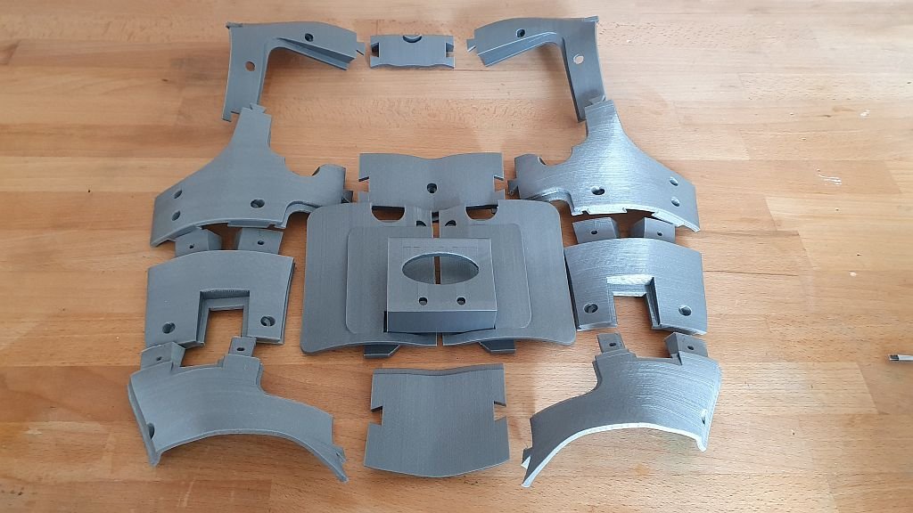
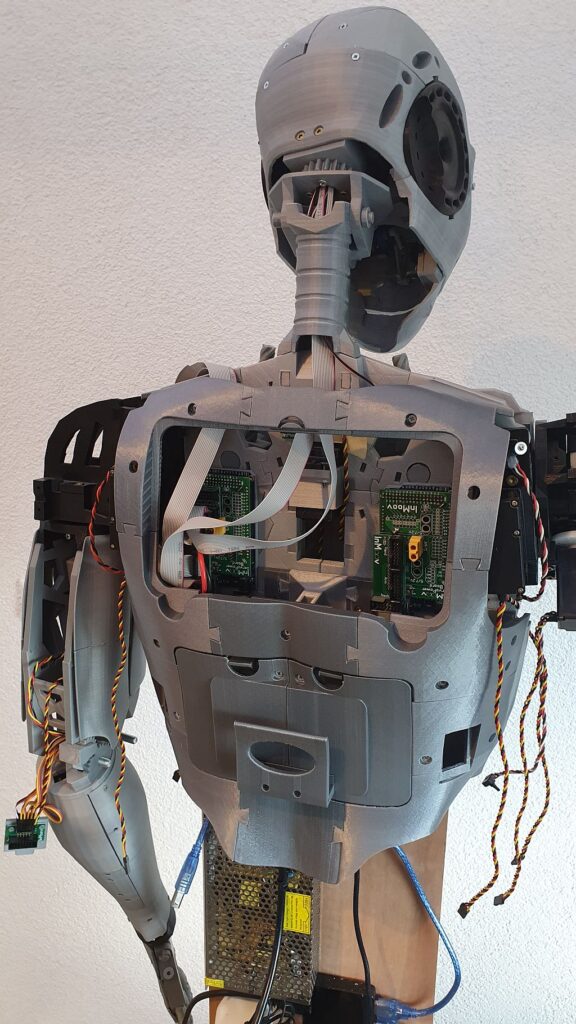
    Now we are going to put the back covers in place. This is a fairly easy build. Just print all parts and clean them up. It’s important to put all the mounts in place first. The panels should be glued together on the robot itself because to prevent to much stress on the parts.

    On the following picture, the parts are layed out as they should be mounted.

    The top part of the back covers should look like this. I used super glue to glue the PLA parts together. Those cheap clamps are usefull to keep everything aligned.

    At the end you should see something like this.

    If you have questions or comments, please let me know. inMoov is designed by Gaël Langevin so make sure you visit is website at https://inmoov.fr.

  • InMoov hand build

    InMoov hand build

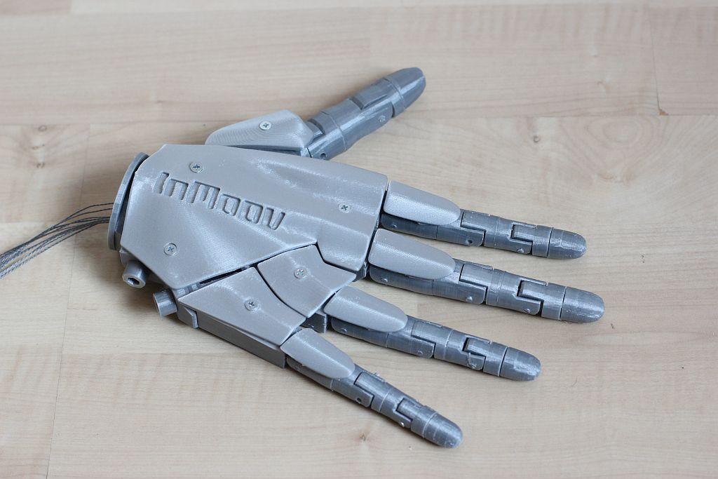
    Finally I made some progress on inMoov robot in a long time. The left arm is completely done already, but the right side still needs the lower arm and the right hand. In this article we going to look at the right hand.

    I made a video with every step of the build in detail, so you can follow along. inMoov is designed by Gaël Langevin so make sure you visit is website at https://inmoov.fr.

    I always print the parts with a brim so it needs a lot of cleanup, but it makes sure the parts are nice and straight. This is important if you need to glue parts together. After cleaning up it’s a good thing to lay all the part on the table to see if everything is there.

    I found it a little bit confusing how the fingers should be glued together, but it’s fairly simple If you know where to look at.

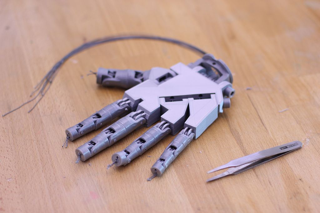
    The lower part of the finger has a marking in the shape of a rectangle when the parts are glued together. The top cap should be glued together with the part with two small holes on the top for the wires. I use hot glue for this part so I can remove the cap if I have to replace the wires someday. For the other parts I used Super Glue. The middle parts of the finger have a shape on the face where the two parts come together.

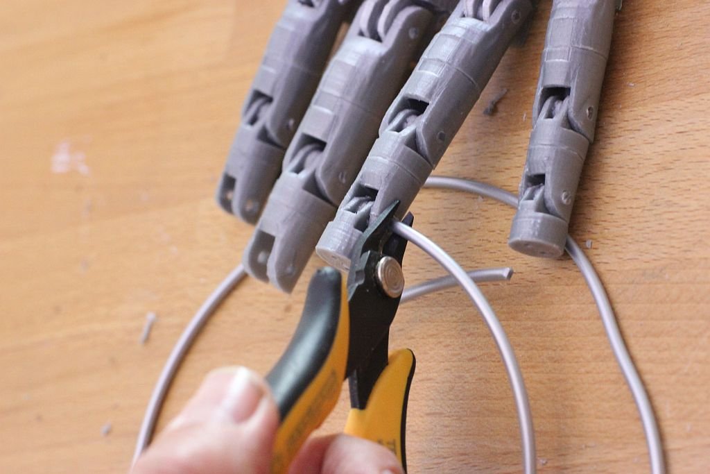
    For the rotating part I used a piece of filament and cut it with a small wire cutter to make a straight cut.

    .

    The other parts are not too complicated to fit together, with help of the picture below.

    You need a tweezer to put the wires through the fingers and the hand. It’s not easy but with some patients it’s not impossible.

    At last I mounted the top of the hand with some 3 mm screws. The 4 parts on the fingers are glued on the fingers. I made the mistake once to glue them on the hand and that looks strange when the hand is in closed position.

    If you have questions or comments, please let me know. inMoov is designed by Gaël Langevin so make sure you visit is website at https://inmoov.fr