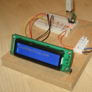
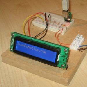
To see what the status is of your robot you can use a variety of displays. In this project we use the LK202-25-WB from Matrix Orbital. (http://www.matrixorbital.com/p57/LK202-25-WB/product_info.html)
This is a 2 line display with 20 characters at both lines. The display has a selectable communication protocol, serial at RS232, TTL levels or I2C.
We use the I2C protocol for this project because this protocol can also be used for sensors and actuators. The communication with a computer with Linux is done by the USB-I2C module from Devantech. (http://www.robot-electronics.co.uk/htm/usb_i2c_tech.htm)
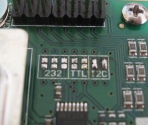
Before you can use the LK202-25 with the I2C protocol you have change the Protocol Jumper setting. As default the jumpers are set to RS-232 mode with solder jumps on the 232 jumpers. To change this you have to remove the three jumpers on the RS232 jumpers and put them on the two I2C jumpers. My soldering iron has a big tip and I could not put the jumpers back properly. I just used a little bit of solder between the two contacts and it works perfectly. (See the picture below)
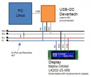
The USB-I2C module delivers only 70 mA of power and is not enough for the LK202-25. Depending of how you use the Display and what color you have a maximum of 148 mA may be required. Therefore an external power source is needed.
The USB-I2C module has integrated pull-up resistors, but because of the external power source additional pull-up resistors are needed. It is important to leave the +5V pin of the USB-I2C module unconnected. See the schematics for how the modules are connected.
Addressing of the LK202-25-WB is slightly different from for example a CMPS03 module from Devantech. The LK202-25 display doesn’t work with registers, so you don’t have to specify this when sending data. The USB-I2C module offers the I2C_SGL command to do this. In the code you see this is done with the 0x53 value.
You can find the code here: MatrixOrbital


